
Heat radiating device

A technology of heat dissipation device and heat dissipation fins, which is applied in cooling/ventilation/heating renovation, instrument cooling, sustainable building, etc., can solve the problem of the decrease in airflow velocity, the inability to effectively improve the heat dissipation efficiency of the heat dissipation device 20, and the reduction of heat dissipation fins. Group 21 and airflow heat exchange efficiency and other issues

Inactive Publication Date: 2007-12-05
FU ZHUN PRECISION IND SHENZHEN +1
View PDF0 Cites 5 Cited by
  • Summary
  • Abstract
  • Description
  • Claims
  • Application Information

AI Technical Summary

Problems solved by technology

As shown by the arrow in the figure, the flow direction of the airflow to the heat dissipation fins 211 outside the dotted line box in the figure is approximately parallel to the heat dissipation fins 211 there, and flows to the heat dissipation fins 211 in the dotted line box in the figure. However, the flow direction forms an included angle with the heat dissipation fins 211 there, causing the airflow flowing to this place to collide with the heat dissipation fins 211 there, causing the airflow to lose a certain amount of kinetic energy, and the flow velocity of the airflow will drop significantly. The heat exchange efficiency between the heat dissipation fin group 21 and the airflow is reduced, resulting in that the heat dissipation efficiency of the heat dissipation device 20 cannot be effectively improved, so it needs to be improved

Method used


Image

  • Heat radiating device
  • Heat radiating device
  • Heat radiating device

Examples


Embodiment Construction

[0012] The present invention will be further described below in conjunction with the embodiments with reference to the accompanying drawings.

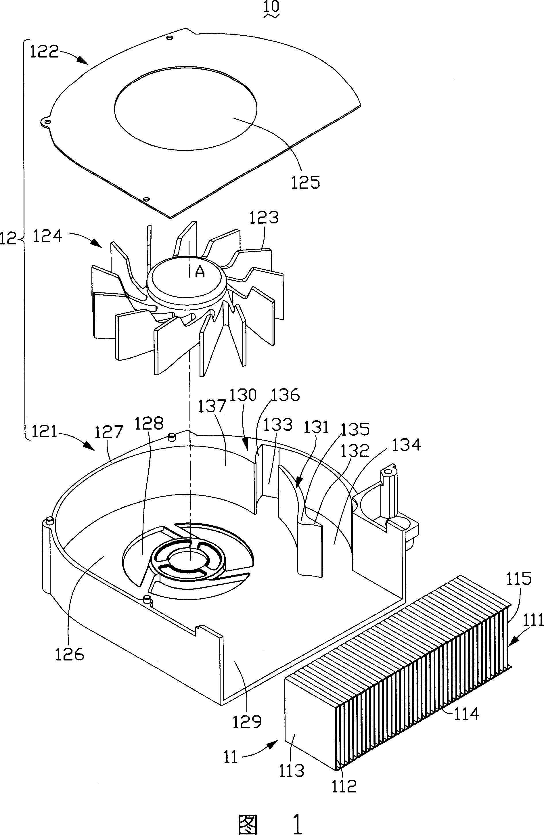
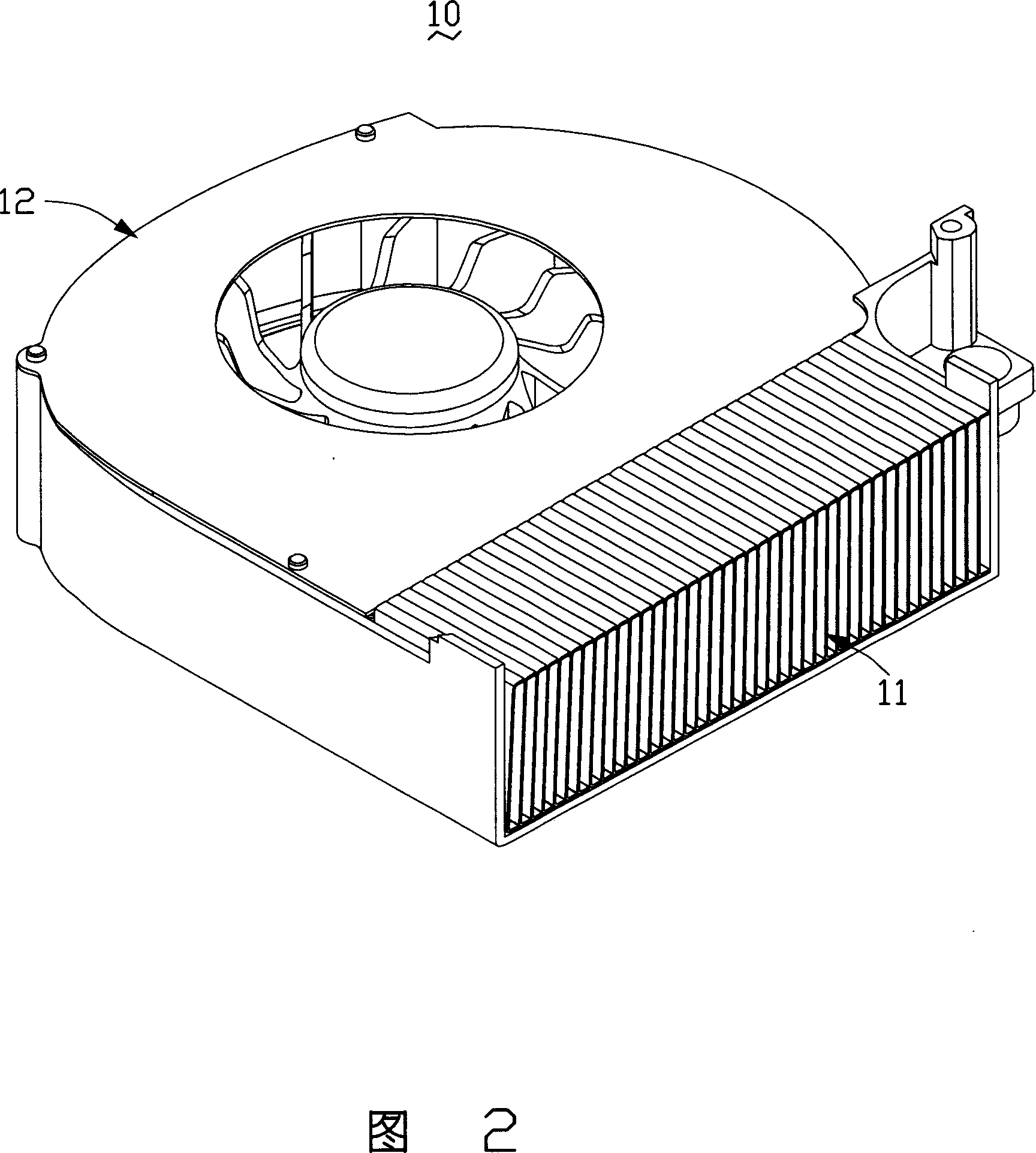
[0013] Please refer to FIG. 1 and FIG. 2 , the heat dissipation device 10 of the present invention includes a heat dissipation fin set 11 and a centrifugal fan 12 . The cooling fin set 11 is thermally connected with a heating electronic component (not shown) to absorb the heat generated by the heating electronic component. The heat absorbed by the fin set 11 is dissipated into the surrounding air.

[0014] The centrifugal fan 12 includes a casing 121 , a cover 122 disposed on the casing 121 , and a rotor 124 having a plurality of fan blades 123 . The cover 122 and the casing 121 form an accommodating space, and the rotor 124 is disposed in the accommodating space and rotates counterclockwise. The cover 122 is provided with a through hole as the air inlet 125 of the centrifugal fan 12, the housing 121 includes a bottom plate 126 and a...


PUM


Abstract

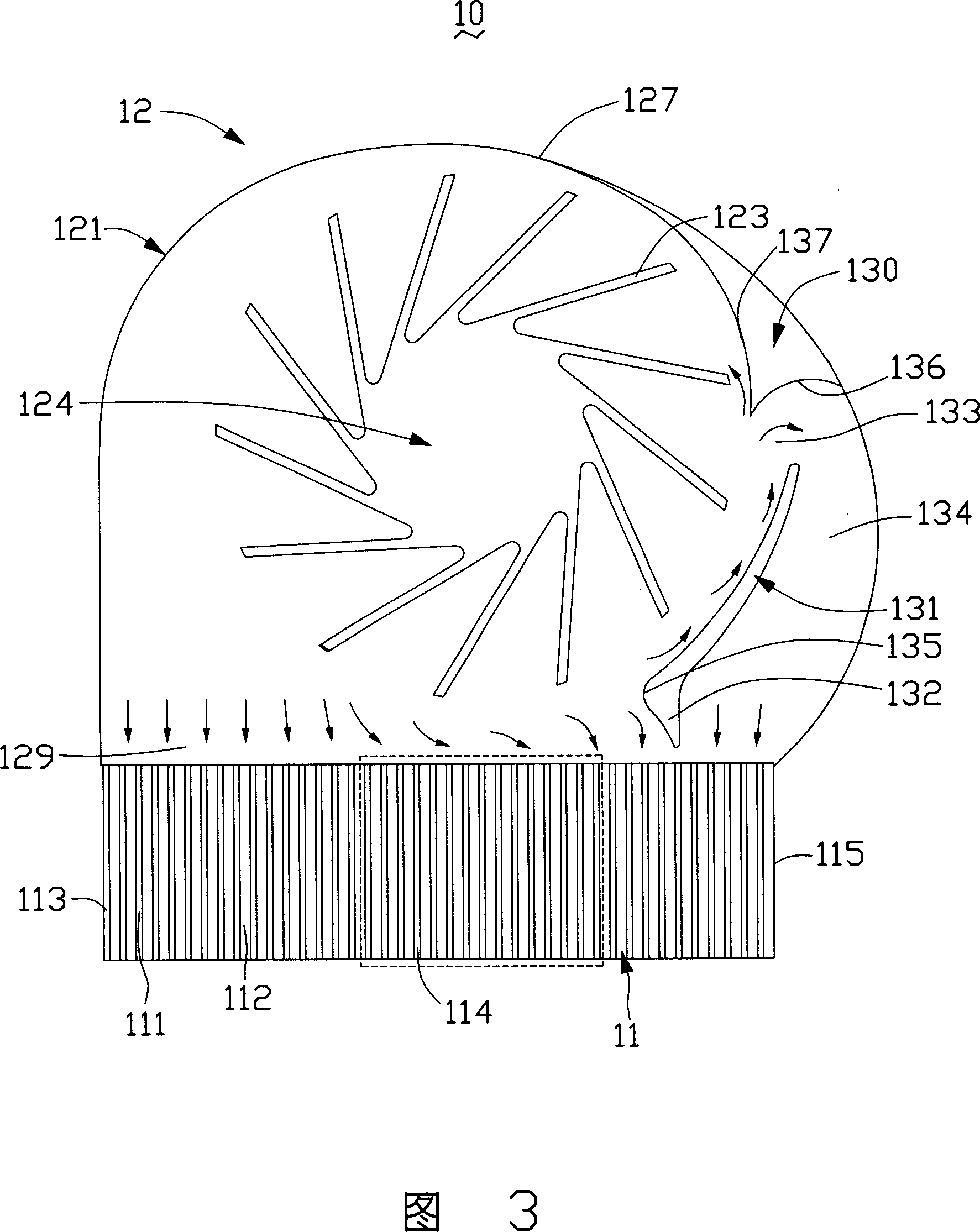
The present invention is a kind of heat-scattered device, including a centrifugal fan and a radiating fin group located at outlet of the fan. The radiating fin group is composed of several parallel radiating fins. The centrifugal fan includes a rotor with several flabellate which is designed to bring a first tongue outlet and a second tongue outlet, of which the first tongue outlet is away from the radiating fin group, the second tongue outlet is located between the first tongue outlet and the outlet of fan. The first and second tongue outlets can induce the airflow caused by the centrifugal fan parallel to the radiating fin group and reduce the energy loss caused by collision of airflow and radiating fin group, thus the airflow velocity will not obviously decreased, and will be easier to get through the surface of radiating fin group, and the radiating effect of the heat-scattered device can be improved.

Description

technical field [0001] The invention relates to a heat dissipation device, in particular to a heat dissipation device for dissipating heat from heating electronic components. Background technique [0002] With the continuous improvement of the power of electronic components such as central processing unit (CPU), the problem of heat dissipation is more and more paid attention to by people, especially in notebook computers. In order to efficiently remove the heat generated by the system in a limited space, the current industry mainly uses a combination of heat dissipation fins, heat pipes and heat dissipation fans for heat dissipation. The heat conduction path of this method is: the heat generated by the CPU is transmitted to the cooling fin set through the heat pipe, and then the airflow generated by the cooling fan will take away the heat transferred to the cooling fin set, so the matching of the cooling fan and the cooling fin set is right The cooling performance of the sy...

Claims


Application Information

Patent Timeline
Patent Type & Authority Applications(China)
IPC IPC(8): H05K7/20H01L23/367G06F1/20G12B15/06
CPCY02B60/1275Y02D10/00
Inventor 黄清白孟劲功林然
Owner FU ZHUN PRECISION IND SHENZHEN
Learn More