Injection mechanism for injection machine

A technology of injection molding machine and injection cylinder, applied in the field of injection mechanism of injection molding machine, can solve the problems of limited injection precision, poor action stability, short service life, etc., and achieve the effect of rapid and stable injection, high precision and long service life

Inactive Publication Date: 2007-12-12
CHANGSHENGDA MASCH ZHEJIANG CO LTD
View PDF1 Cites 13 Cited by
  • Summary
  • Abstract
  • Description
  • Claims
  • Application Information

AI Technical Summary

Problems solved by technology

[0005] In order to overcome the short service life of the injection mechanism of the existing injection molding machine, easy to be damaged by improper adjustment of the nozzle center, poor movement stability, and limited injection accuracy, the present invention provides a long service life, which is not easy to be caused by improper adjustment of the nozzle center. The injection mechanism of the injection molding machine with more rapid and stable injection and high precision

Method used


Image

  • Injection mechanism for injection machine
  • Injection mechanism for injection machine
  • Injection mechanism for injection machine

Examples


Embodiment Construction

[0020] The present invention will be further described below in conjunction with the accompanying drawings.

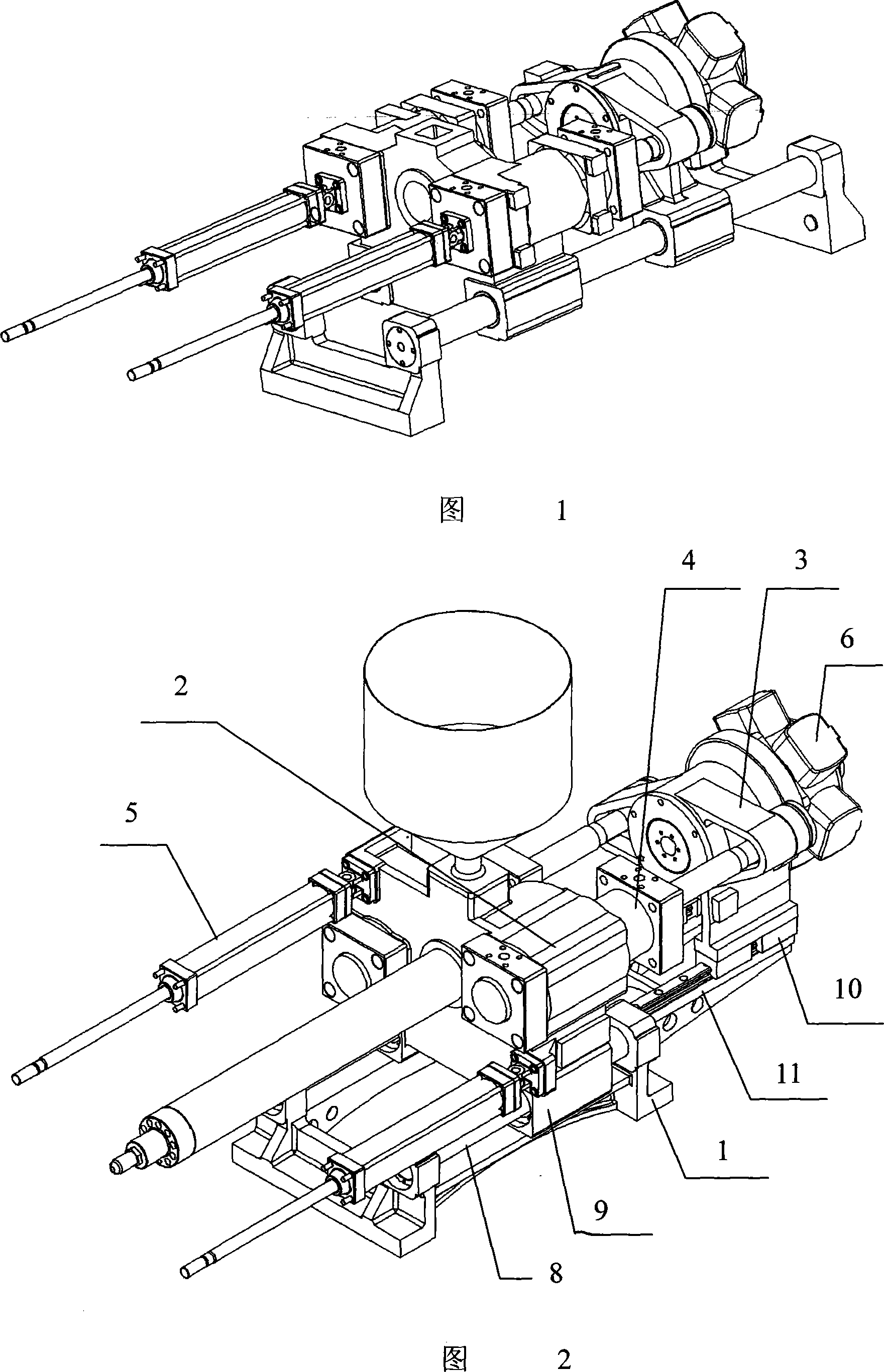
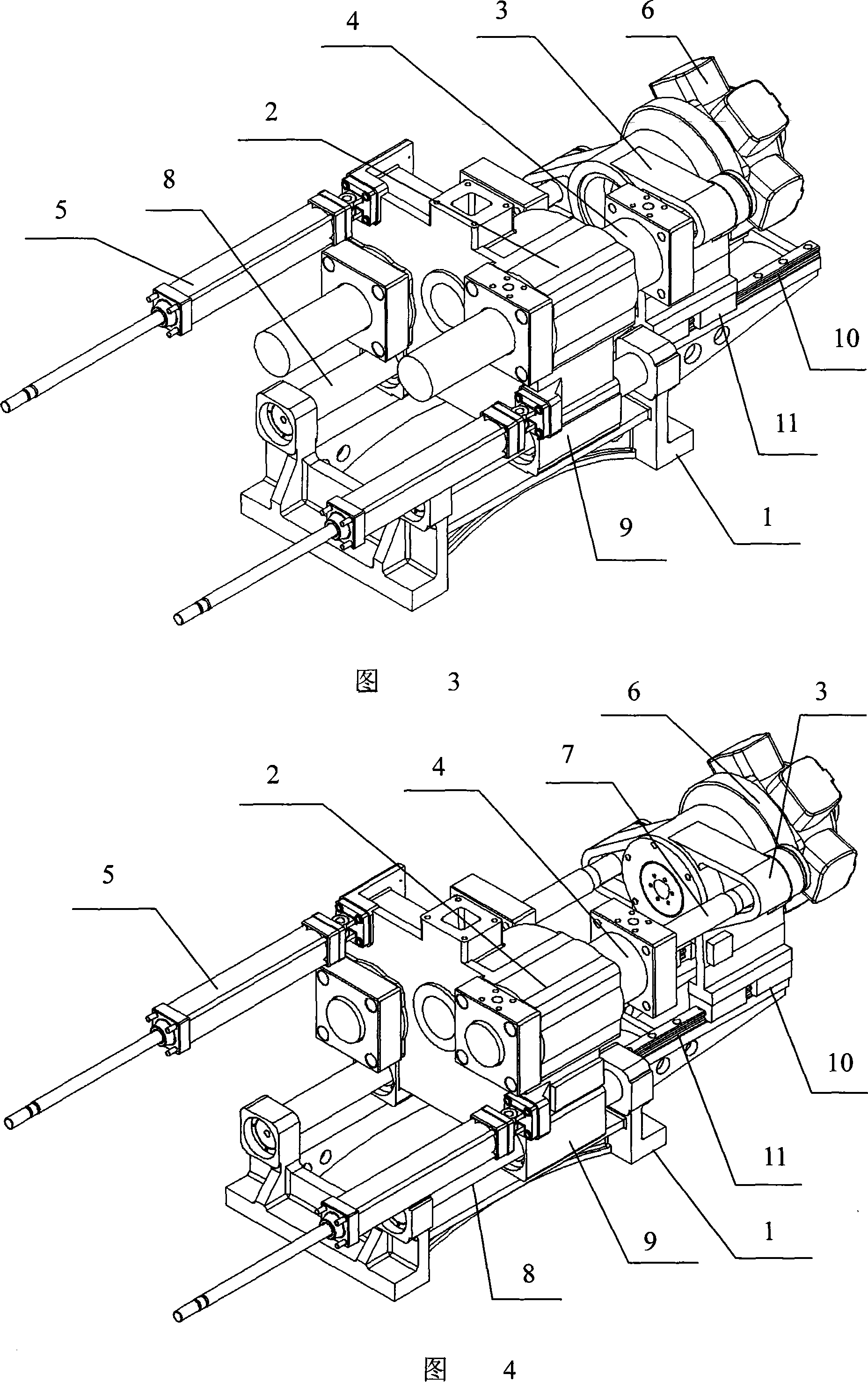
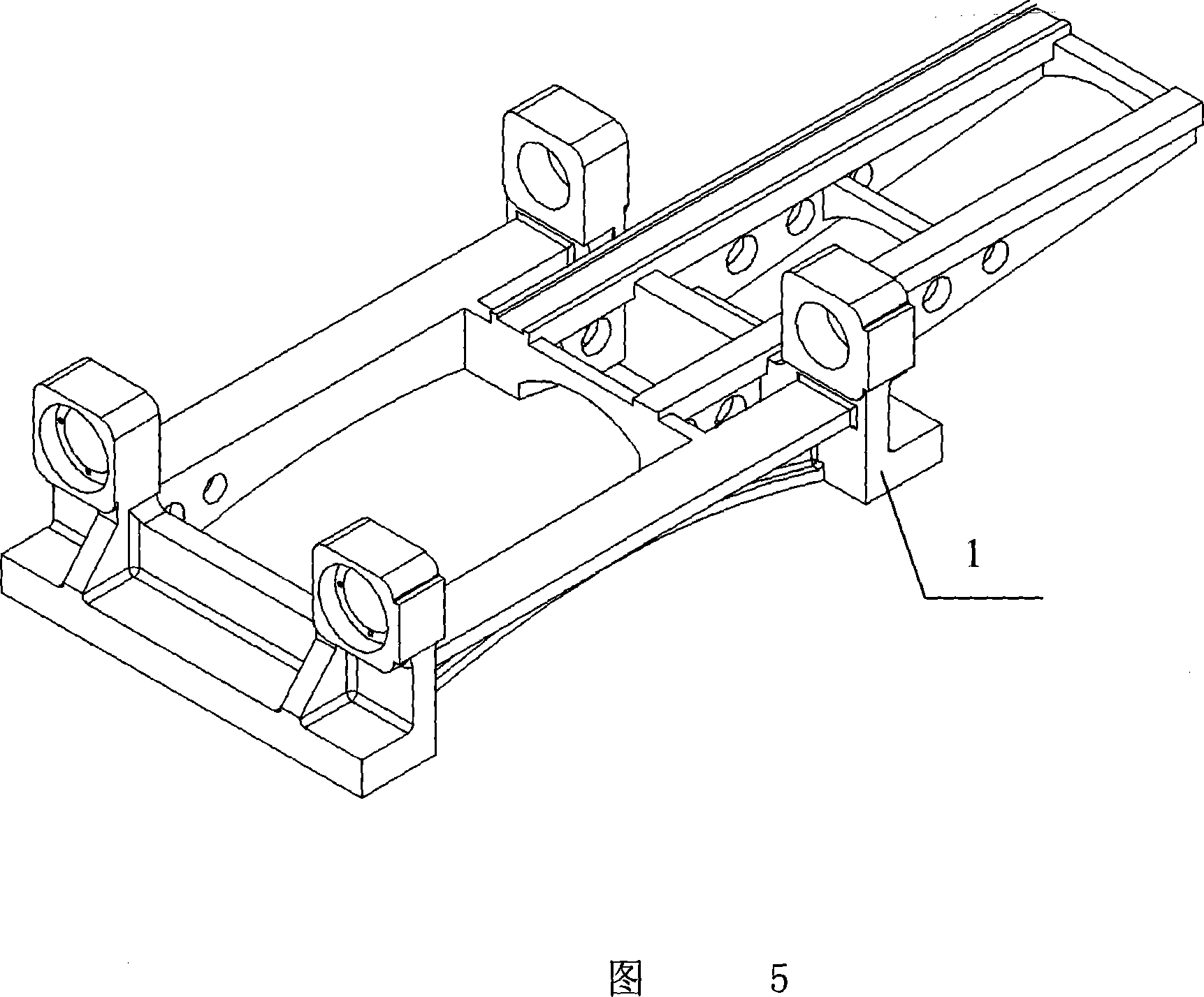
[0021] Referring to Figures 2 to 6, an injection mechanism of an injection molding machine includes an injection platform support 1, an injection platform front plate 2 located on the injection platform support 1, and an injection platform rear plate 3, and the injection platform front plate 2 The injection cylinder group 4 and the moving cylinder group 5 are installed on the top, and the oil motor 6 and the injection piston rod 7 are installed on the rear plate 3 of the injection platform. The injection piston rod 7 is connected with the injection cylinder group 4. The injection platform The bottom of the front plate 2 is provided with a sleeve 8, the sleeve 8 is slidably set on the guide rod 9, and the guide rod 9 is installed in front of the shooting platform support 1; the shooting platform rear plate 3 A slide block 10 is provided at the bottom of the bottom, and ...


PUM


Abstract

The injecting structure of the injection machine comprises the ejection table bracket, front panel on the bracket, rear plate of the injection table, injection oil cylinder set on the front plate of the injection plate, displacing the oil cylinder set, installing oil motor, injection piston rod on the rear plate of the injection plate, with the said injection piston rod connected with the injection oil cylinder, sleeve tube at the bottom of the front panel of the injection plate, the sleeve tube set on the guide pole slidilingly, with the guide pole at the front of the injection bracket, sliders at the bottom of the injection rear plate, sliders slidingly connected with the linear guide track that is installed at the rear of the injection bracket. It is durable, hard to cause damage to improper adjustment of the nozzle center, more agile and stable injection, and high precision injection machine injecting structure.

Description

(1) Technical field [0001] The invention relates to the field of injection molding machines, in particular to an injection mechanism of an injection molding machine. (2) Background technology [0002] The existing injection molding machines are basically guided by two parallel guide rods, as shown in Figure 1, and the guide rods also carry the weight of the injection parts and the weight of the raw materials while guiding. direction deformation, which greatly reduces the accuracy of injection and storage; and the clearance fit between the guide rod and the guide sleeve has determined that the accuracy of the structure is limited, and the friction between them is sliding friction. As time goes on, the accuracy will become lower and lower. [0003] Another example is the Chinese Patent No.: 02265526.3, the invention name is an improved utility model patent for the pre-molding guide system of an injection molding machine, which discloses a guide system that can reduce friction...

Claims


Application Information

Patent Timeline
Patent Type & Authority Applications(China)
IPC IPC(8): B29C45/46B29C45/53
Inventor 陈一青
Owner CHANGSHENGDA MASCH ZHEJIANG CO LTD
Why Eureka
Try Eureka