Power supply circuit, charge pump circuit, and portable appliance therewith

A charge pump and circuit technology, applied in the direction of conversion equipment without intermediate conversion to AC, can solve problems such as unfavorable voltage drop, unstable operation, etc., and achieve the effect of reducing inrush current

Inactive Publication Date: 2007-12-12
ROHM CO LTD
View PDF1 Cites 19 Cited by
  • Summary
  • Abstract
  • Description
  • Claims
  • Application Information

AI Technical Summary

Problems solved by technology

[0005] One problem with this charge pump circuit is the inrush current at start-up
Especially in systems with high-impedance power supply parts, such as portable devices powered by batteries as their power source, the inrush current unfavorably causes a voltage drop in the voltage supplied to different parts of the device, making operation unstable

Method used


Image

  • Power supply circuit, charge pump circuit, and portable appliance therewith
  • Power supply circuit, charge pump circuit, and portable appliance therewith
  • Power supply circuit, charge pump circuit, and portable appliance therewith

Examples


Embodiment Construction

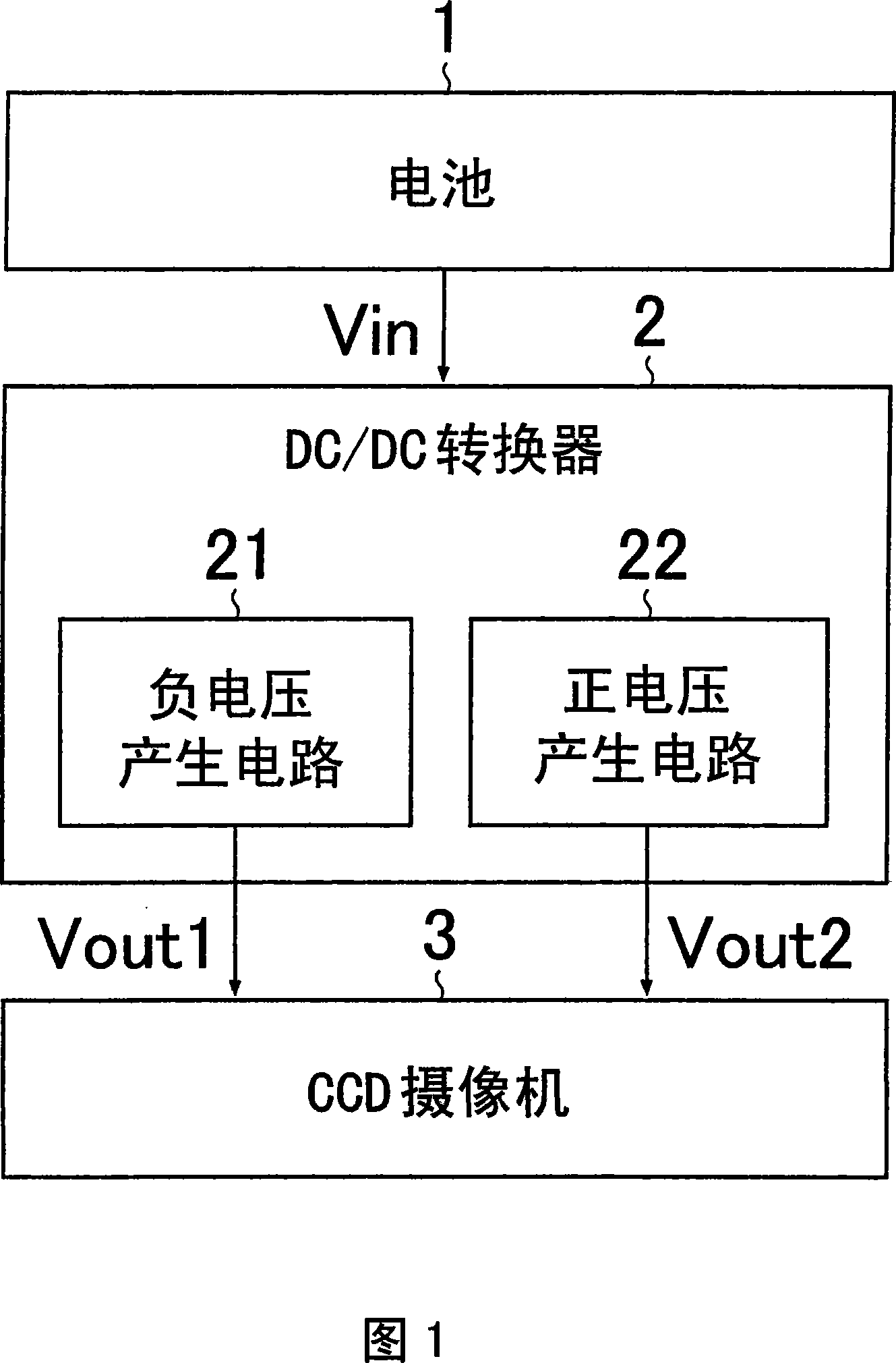
[0075] Next, by its application to the DC / DC converter contained in the cellular phone unit in order to convert the output voltage of the battery to generate the voltage for driving the different parts of the cellular phone unit, specifically the CCD (Charge Coupled Device) camera Examples are used to describe the present invention.

[0076] FIG. 1 is a block diagram showing a cellular phone unit (specifically, a power supply portion of a CCD) according to the present invention as an embodiment of the present invention. As shown in the figure, the cellular phone unit of this embodiment includes: a battery 1 used as a power source for the entire cellular phone unit; a DC / DC converter 2 used as a device for converting the output of the battery 1; and a CCD camera 3 used as a power source for the entire cellular phone unit; A cellular phone unit is a device for sensing images. Needless to say, the cellular phone unit includes a transmission / reception circuit, a speaker, a microp...


PUM


Abstract

A charge pump circuit (21) is composed of transistors (P1-P3) connected parallel between one end of a capacitor (C1) and an input terminal (T1) as a switching means to be turned on at the time of charging the capacitor (C1). A control section (CNT) decides which of the transistors (P1-P3) to drive at the time of charging the capacitor (C1), based on input / output voltage monitoring results from first and second detectors (DET1, DET2). Thus, even when a voltage level of an input voltage fluctuates, a rush current generated at start-up can be reduced without causing deterioration in output voltage and efficiency.

Description

technical field [0001] The present invention relates to a charge pump circuit for use as a DC / DC converter, in particular as a battery output conversion device in portable equipment. Background technique [0002] FIG. 8 is a circuit diagram showing a conventional example of a charge pump circuit. The charge pump circuit shown in the figure is configured to periodically turn on and off the switches SW1 to SW4 to charge the first capacitor C1 with the input voltage Vin fed through the input terminal, and the charging voltage across the first capacitor C1 Feed out via the output terminal as negative voltage Vout(-Vin). [0003] More specifically, here, the negative voltage is output in the following manner. First, the switches SW1 and SW2 are turned on, and the switches SW3 and SW4 are turned off. As a result of this switching, the input voltage Vin is applied to the first end (point A) of the first capacitor C1 via the switch SW1, and the second end (point B) of the first c...

Claims


Application Information

Patent Timeline
Patent Type & Authority Applications(China)
IPC IPC(8): H02M3/07
CPCH02M3/07
Inventor 柳田修今中义德
Owner ROHM CO LTD
Why Eureka
Try Eureka