

Rotary painting glue applying device and method
A technology of spin coating and glue dispensing, which is applied to the device and coating of the surface coating liquid, which can solve the problems of pinching the lens module, inaccurate positioning, and large structure of the glue dispensing device, so as to speed up the glue dispensing process , Reduce the required space and save the dispensing time
- Summary
- Abstract
- Description
- Claims
- Application Information
AI Technical Summary
Problems solved by technology
Method used
Image

Examples
Embodiment Construction
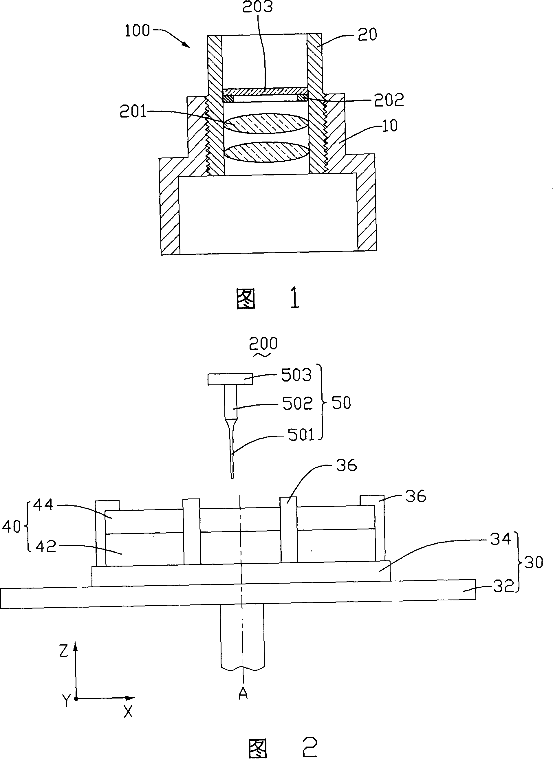
[0015] A spin-coating dispensing device and a spin-coating dispensing method using the spin-coating dispensing device will be described below with examples.
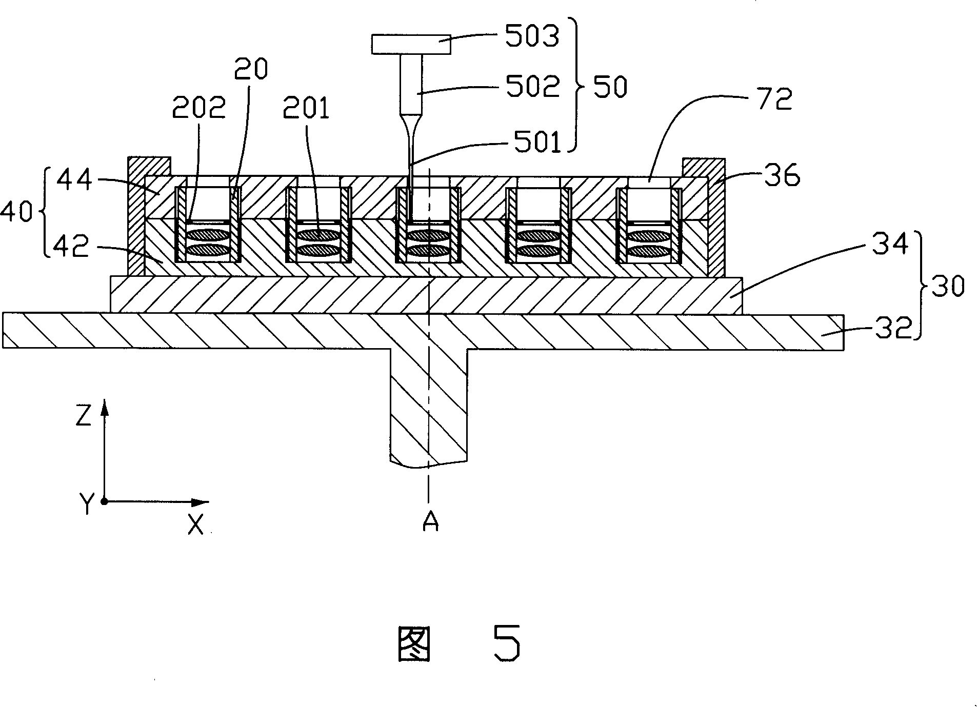
[0016] Please refer to FIG. 2 , which is a spin coating dispensing device 200 provided in this embodiment, which includes a working machine 30 , a holding device 40 and a dispensing mechanism 50 .
[0017] The working platform 30 includes a rotating platform 32 and a horizontally moving part 34 .
[0018] The rotating platform 32 is rotatable around its central axis A of rotation.
[0019] The horizontal moving part 34 is fixed on the upper surface of the rotating platform 32 and driven by a stepping motor controlled by a computer, and can move in horizontal X and Y directions to adjust its position on the rotating platform 32 . The horizontal moving part 34 can be positioned on the rotation central axis A of the rotating platform 32 by controlling the displacement in the X and Y directions, so that the rotating platfor...
PUM
 Abstract
Description
Claims
Application Information