High efficient laminated graphic discharge gap device

A discharge gap, stacked technology, applied in circuits, spark gaps, electrical components, etc., can solve the problem of not determining the discharge electrode material, not explaining the spark arc suppression problem, and the uncertainty of the fixed value or value range of the grading capacitor. and other problems, to achieve the effect of controlling ignition breakdown voltage, protecting safety, and no arc leakage

Active Publication Date: 2007-12-19
SICHUAN ZHONGGUANG LIGHTNING PROTECTION TECH
View PDF2 Cites 39 Cited by
  • Summary
  • Abstract
  • Description
  • Claims
  • Application Information

AI Technical Summary

Problems solved by technology

This kind of spark gap device has the following disadvantages: 1. Due to the uncertainty of CL in the above formula, it brings uncertainty in the fixed value or value range of the voltage equalizing capacitor; 2. The above formula is based on 1.2/ The reference improvement value under the im

Method used


Image

  • High efficient laminated graphic discharge gap device
  • High efficient laminated graphic discharge gap device
  • High efficient laminated graphic discharge gap device

Examples


Embodiment 1

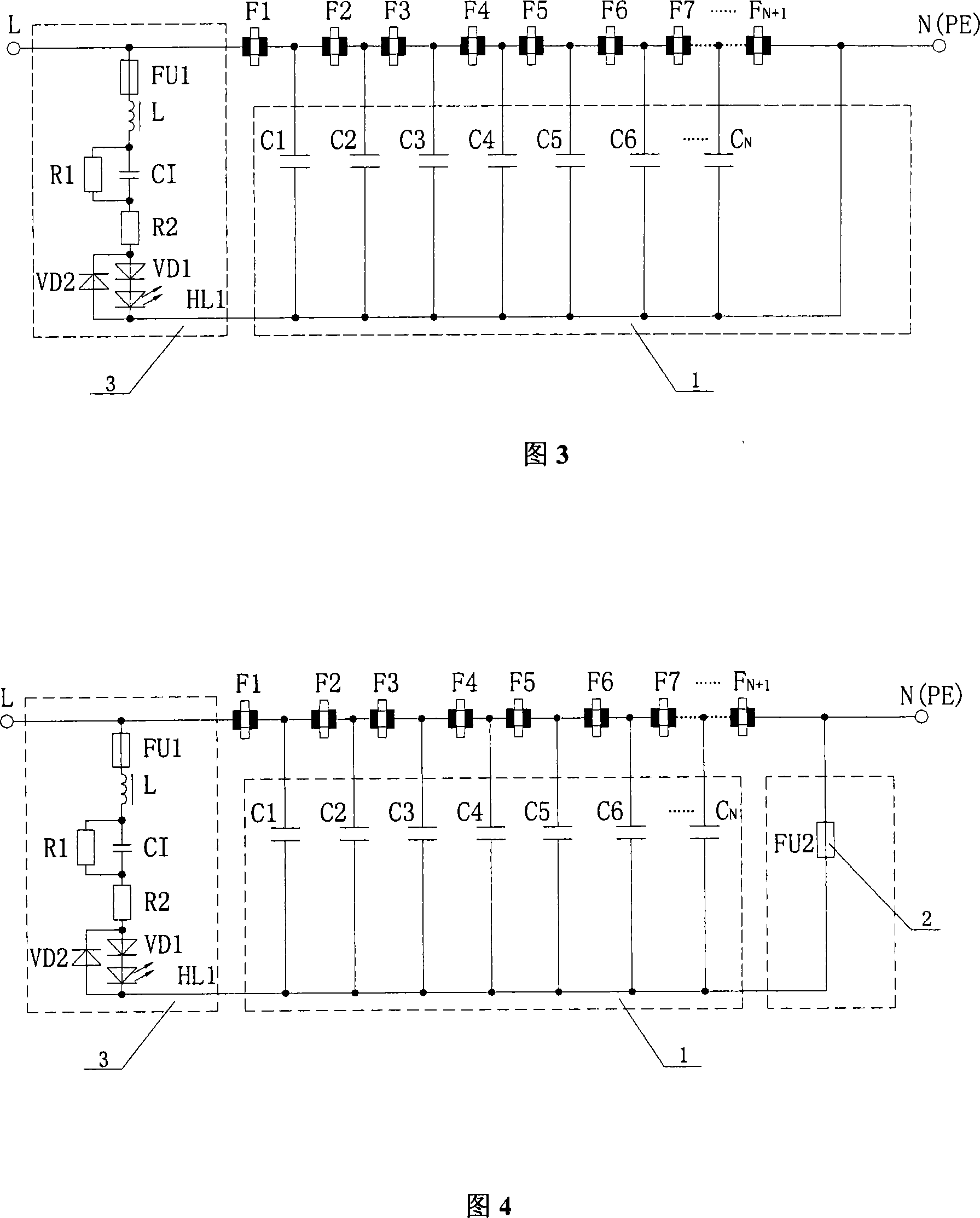
[0056] The circuit structure of the high-efficiency graphite laminated discharge gap device in this embodiment is shown in Figure 4, including eight graphite discharge gaps, a π-shaped connection capacitor group 1 composed of seven capacitors with the same capacitance value, a current fuse 2 and an indication Circuit 3. Each graphite discharge gap is connected in series, wherein, the first graphite discharge gap F 1 Connect with live wire, the last discharge gap F 8 Grounded, π-shaped connection to each capacitor C in the capacitor bank 1 、C 2 、C 3 、C 4 、C 5 、C 6 、C 7 One end is connected to the conductive part between the two graphite discharge gaps, and the other end is grounded; the end of the π-shaped connection capacitor group circuit is connected to the current fuse 2; one end of the indicating circuit is connected to the first graphite discharge gap F 1 On the connecting piece with the live wire L, the other end is grounded. The structure of the indicating circ...

Embodiment 2

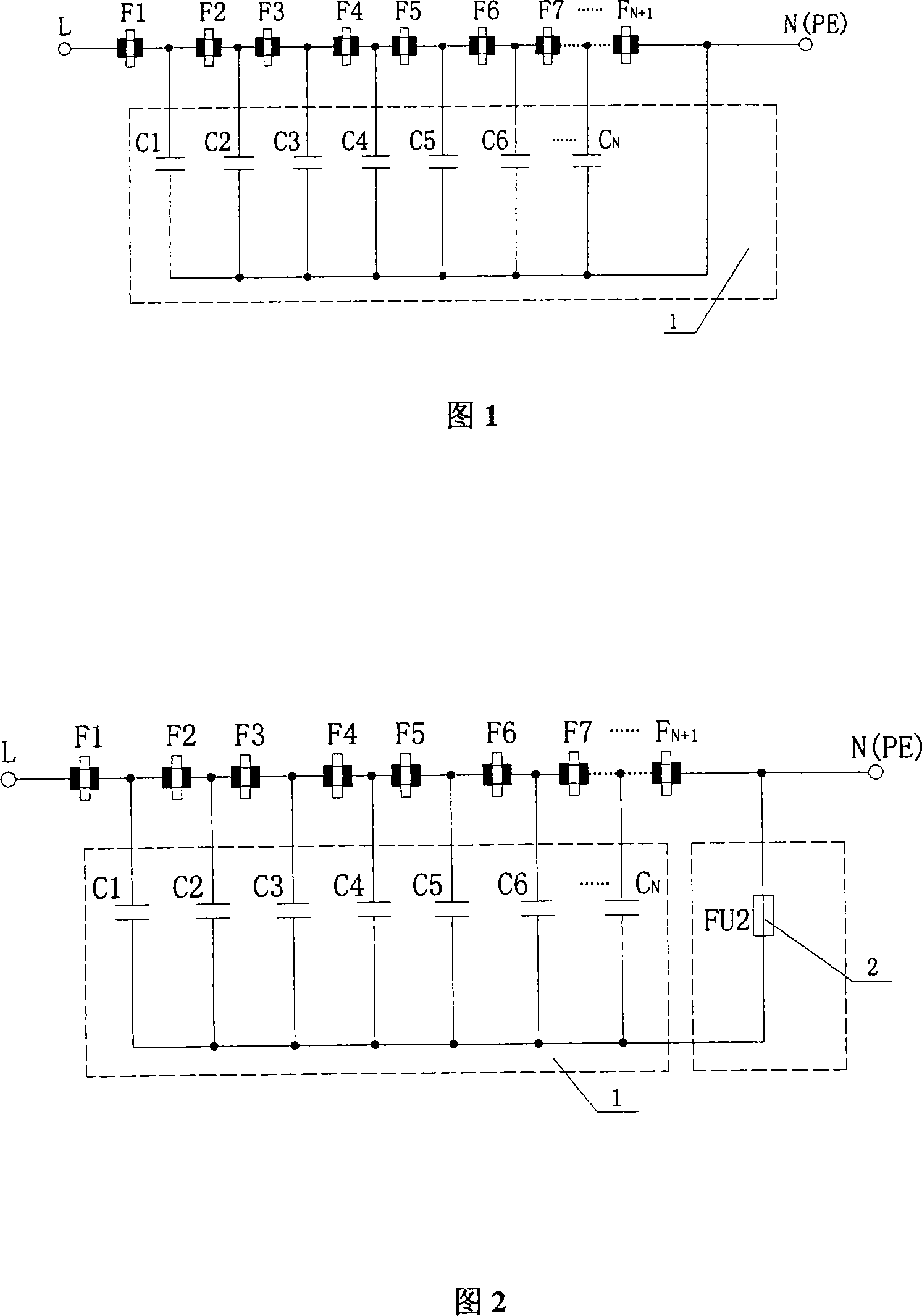
[0060] The circuit structure of the high-efficiency graphite stacked discharge gap device in this embodiment is shown in Figure 1, including nine graphite discharge gaps and a π-shaped connection capacitor group 1 composed of eight capacitors with the same capacitance value, and each graphite discharge gap is connected in series , where the first graphite discharge gap F 1 Connect with live wire, the last discharge gap F 9 Grounding, one end of each capacitor in the π-shaped connection capacitor group is connected to the conductive member between the two graphite discharge gaps, and the other end is grounded.

[0061] In the above circuit, the value of each capacitor of the π-shaped connection capacitor group is determined according to C=In / 2πfVK, where In=I / N=3.2 / 8A, f≈18×10 3 Hz, V=3000V, K=3, into the above formula calculation, C≈390pF.

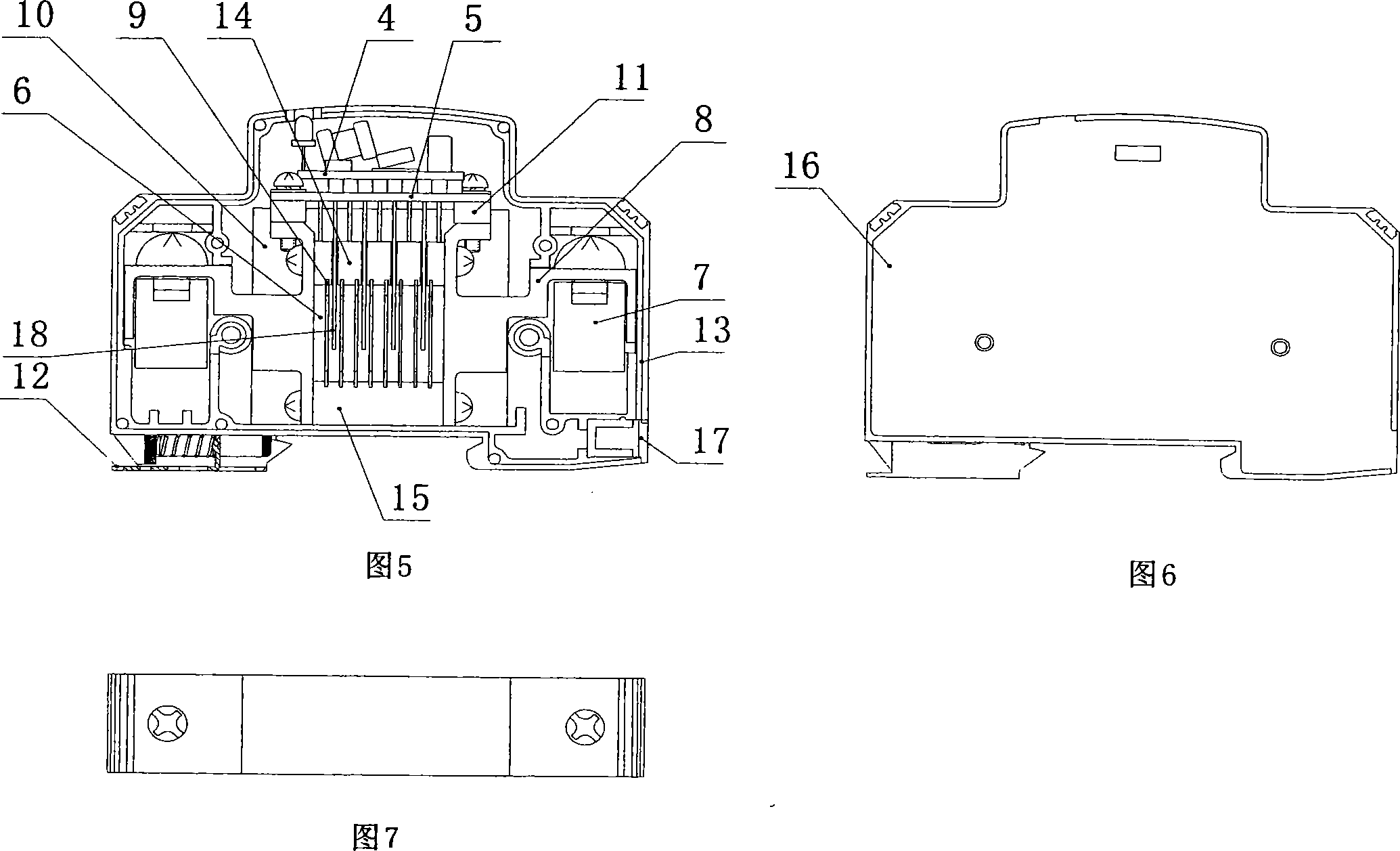
[0062] The electronic components in the above-mentioned circuit are assembled in the box body 13 shown in Figure 5, the size of the box...

Embodiment 3

[0065] The circuit structure of the high-efficiency graphite laminated discharge gap device in this embodiment is shown in Figure 2, including ten graphite discharge gaps, a π-connected capacitor group 1 composed of nine capacitors with the same capacitance value, and a current fuse 2. Each graphite discharge gap is connected in series, wherein, the first graphite discharge gap F 1 Connect with live wire, the last discharge gap F 10 Grounding, one end of each capacitor in the π-shaped connection capacitor group is connected to the conductive member between the two graphite discharge gaps, the other end is grounded, and the end of the π-shaped connection capacitor group circuit is connected to the current fuse 2 .

[0066] In the above circuit, the value of each capacitor of the π-shaped connection capacitor group is determined according to C=In / 2πfVK, where In=I / N=4.5 / 9A, f≈18×10 3 Hz, V=3000V, K=2, into the above formula calculation, C≈737pF.

[0067] The electronic compone...


PUM


Abstract

This invention relates to an efficient laminated graphite discharge arc gap device including: N+1 arc gaps and a pi-shaped connection capacitor set with N capacitors in the same capacitance value, in which, the gaps are serial to each other, the first one is connected with the live wire, the last one is connected to the earth, one end of each capacitor in the set is connected with the conduction piece between the two arc gaps and the other end is connected to the earth, the arc gap is made of graphite, insulation ring pad is set between the graphite electrodes, the arc gaps are assembled in lamination, parameter of each capacitor in the set is selected according to C=In/2pifVK, in which, In is the induced discharge current on the capacitors, In=I/N, I is the total current of the set, N is the number of capacitors, f is a lightning wave frequency, V is a rating voltage and K is a safety factor greater than or equal to 1.

Description

technical field [0001] The invention relates to a discharge gap device carrying lightning current, which is mainly used for the first-level lightning protection of a power supply system, so as to prevent various communication base stations, substations, and power electronic equipment from being damaged by direct lightning or lightning induction. Background technique [0002] There are various structures of lightning protection discharge gap devices currently used. The anti-lightning discharge gap device adopting a single-pole metal (claw horn) gap is one of them. Due to the requirements of the safety distance standard, the metal gap gap of this type of discharge gap device cannot be reduced and increased at will, because there is an irreconcilable contradiction between the safety distance and the discharge voltage for lightning starting; another problem is that this type of device works When the arcing occurs, the surrounding equipment will be seriously damaged by arcing. ...

Claims


Application Information

Patent Timeline
IPC IPC(8): H01T4/16
Inventor 王德言阮建中雷成勇易代献朱成杨国华
Owner SICHUAN ZHONGGUANG LIGHTNING PROTECTION TECH
Why Eureka
Try Eureka