Energy saving method and equipment for rectification separation

A rectification separation and equipment technology, which is applied in the field of energy-saving rectification separation and equipment, can solve the problems of consuming the heat load of the condenser, the heat load of the reboiler, inconvenient start-up operation, and no thermal coupling, etc., so as to reduce the heat load of condensation, The effect of saving heat removal heat load and reducing comprehensive energy consumption

Active Publication Date: 2007-12-26
PETROCHINA CO LTD
View PDF0 Cites 17 Cited by
  • Summary
  • Abstract
  • Description
  • Claims
  • Application Information

AI Technical Summary

Problems solved by technology

[0004] At present, the typical single-column rectification and two-column rectification technologies in series all use standard condensers and reboilers without "thermodynamic coupling" and need to consume the corresponding heat load of the condenser and reboiler. There are needs and possibilities for improvement
[0005] At present, "intermediate reboiler" technology is used in single-column distillation, but its heat source comes from other parts, not from the rectification column system itself, and it is inconvenient to start and operate, so it needs to be improved
[0006] At present, in the single-column distillation, there is a "double-column double-pressure parallel condenser/reboiler thermal coupling technology", but this method will bring inconvenience to the operation, because an almost identical column is connected in parallel, so that The operation is complicated; and because of

Method used


Image

  • Energy saving method and equipment for rectification separation
  • Energy saving method and equipment for rectification separation
  • Energy saving method and equipment for rectification separation

Examples


Embodiment 1

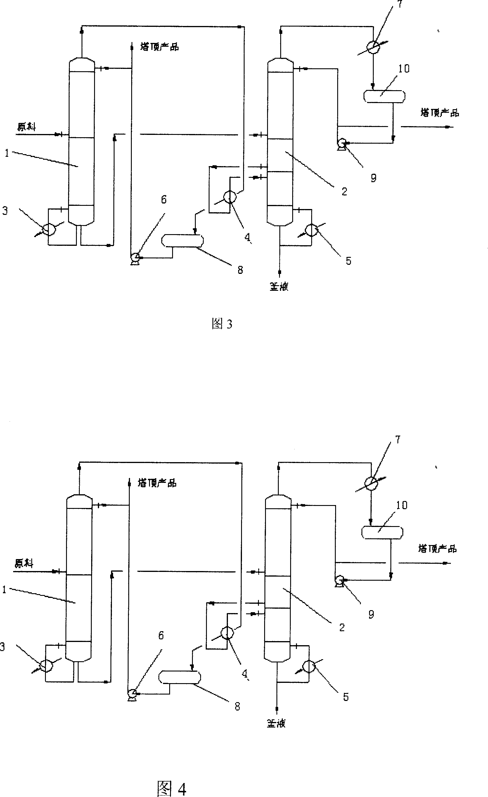
[0030] In this embodiment, the single-column rectification column is changed to a double-column double-pressure series connection, a condenser and an intermediate reboiler are thermally coupled, and an additional reboiler is adjusted. The flow diagram is shown in Figure 3.

[0031] It is composed of two rectification towers A and B, the bottom of tower A (1) is connected with a reboiler (3), the outlet at the bottom of the tower is connected with the inlet of tower B (2), and the outlet at the top of tower A is connected with The intermediate reboiler (4) is connected, the intermediate reboiler is connected with a reflux tank (8), the reflux tank is connected with the top inlet of the A tower through the reflux pump (6), and the intermediate reboiler is connected with the lower part of the B tower. One end of the adjustable reboiler (5) is connected to the bottom of the B tower, and the other end is connected to the still liquid outflow pipeline at the bottom of the B tower. P...

Embodiment 2

[0034] In this embodiment, the double-tower rectification tower is changed to a double-tower double-pressure series connection, a condenser and an intermediate reboiler are thermally coupled, and an additional adjustment is made to the reboiler. When the feed is in the A tower, the flow diagram is shown in Figure 4, and the process The flow process is as in Example 1. The fresh raw material first enters the A tower, and the product I is evaporated from the top of the tower. After being deheated and condensed by the condenser and the intermediate reboiler of the B tower, it enters the reflux tank for buffering, and part of the reflux returns to the top of the tower. For production of product I, the tower is equipped with a typical reboiler, and the still liquid is taken out and enters tower B. Tower B steams light product II from the top of the tower. The classic condenser removes heat and condenses, and enters the reflux tank for buffering. Part of the reflux returns to the top...

Embodiment 3

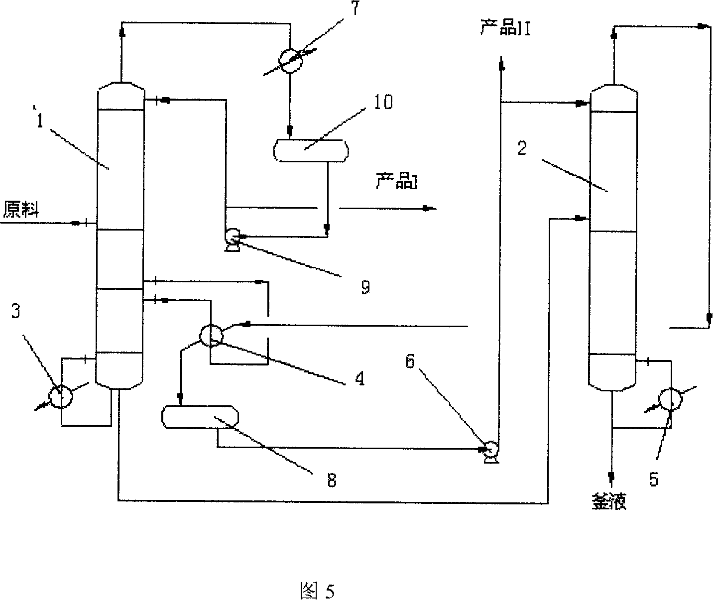
[0036]In this embodiment, the double-tower rectification tower is changed to a double-tower double-pressure series connection, a condenser and an intermediate reboiler are thermally coupled and an additional adjustment of the reboiler process is carried out. The process equipment is the same as in Example 1. When the feed is in the B tower, Referring to accompanying drawing 5, fresh raw material enters tower B at first, and product I is steamed out at the top of the tower, is deheated and condensed by the typical condenser of tower B, enters the reflux tank for buffering, and part of the reflux returns to the top of the tower, and the remainder is extracted as product I. An additional regulating reboiler is added at the bottom of the tower to ensure the normal operation of the B tower. The liquid in the bottom of the tower is taken out and enters the A tower. The boiler removes heat, condenses, enters the reflux tank for buffering, part of the reflux returns to the top of the t...


PUM


Abstract

The invention relates to an equipment and method for saving energy conservation in selective evaporation. The equipment involves A and B rectification tower in series. The bottom of Tower A connects the reboiler. The export of Tower A connects the import of Tower B. The export of Tower A on the top connects middle reboiler, reflux accumulator, reflux pump. The bottom of Tower B connects middle reboiler. The top of Tower B connects condenser, reflux accumulator, reflux pump. The heat of condensation of Tower A is as the load of middle reboiler when connected Tower B. Part of the heat of condensation reflows to the tower and other is as the product. In Tower B, the light product boils over from the top. Some reflows to tower and other is as the product. The heat is from condenser and middle reboiler and attaches the light-load adjustment reboiler to achieve connecting in series, the mightiness coupling between condenser and middle reboiler. The design is reasonable; the effect on saving energy is obvious.

Description

Technical field: [0001] The invention relates to an energy-saving rectification separation method and equipment for rectification separation. Background technique: [0002] The current schematic flow chart of a typical single-column rectification is shown in Figure 1. The raw materials are separated through the rectification tower, the top product is obtained from the top of the tower, and the bottom product is obtained from the bottom of the tower. [0003] The current schematic flow chart of a typical series-connected two-tower rectification is shown in Figure 2. The raw material enters the rectification tower I, and the tower top product I is obtained from the top of the tower, and the tower bottom liquid enters the rectification tower II, and another tower top product II is obtained from the top of the rectification tower II, and the tower bottom is obtained from the tower bottom product. [0004] At present, the typical single-column rectification and two-column rect...

Claims


Application Information

Patent Timeline
IPC IPC(8): B01D3/14
Inventor 陈振京曹坚杨维军陈伟刘一心
Owner PETROCHINA CO LTD
Why Eureka
Try Eureka