Aerator for flat-bottomed water release structure

A technology for drainage structures and aeration devices, which is applied in the field of aeration devices, can solve the problems of reducing the effective height of upstream sills, unfavorable water accumulation, and affecting the air aeration effect, etc., so as to increase the effective sill height and reduce air intake. The effect of cavity return water and improving air entrainment efficiency

Inactive Publication Date: 2007-12-26
HOHAI UNIV
View PDF0 Cites 10 Cited by
  • Summary
  • Abstract
  • Description
  • Claims
  • Application Information

AI Technical Summary

Problems solved by technology

It can be seen from Figure 5 that the wedge-shaped body abcd forms the flow sill (B), if its upstream side (side ad) is made vertically upward, then point a is higher than the water tongue and the flow sill to a certain extent The impact point (b point) is equivalent to reducing the effective height of the upstream ridge; the upstream side (ad) is vertically upward, which is not conducive to the air to bring out the accumulated water in the cavity; the part in the cavity (abd) is not Facilitate the flow of airflow and affect the aeration effect

Method used


Image

  • Aerator for flat-bottomed water release structure
  • Aerator for flat-bottomed water release structure
  • Aerator for flat-bottomed water release structure

Examples


Embodiment

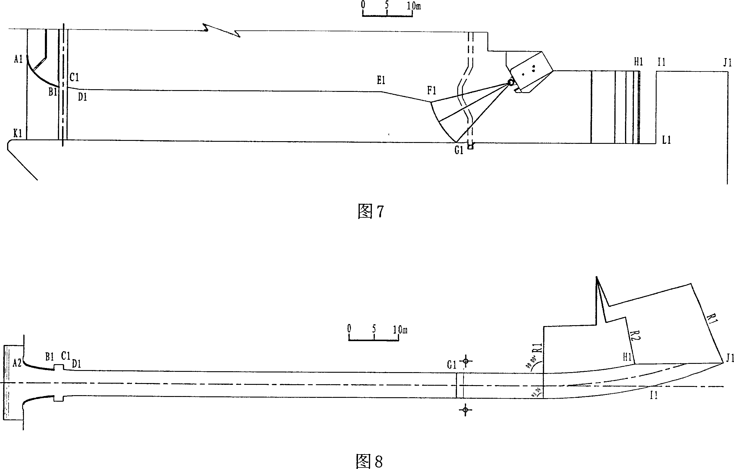
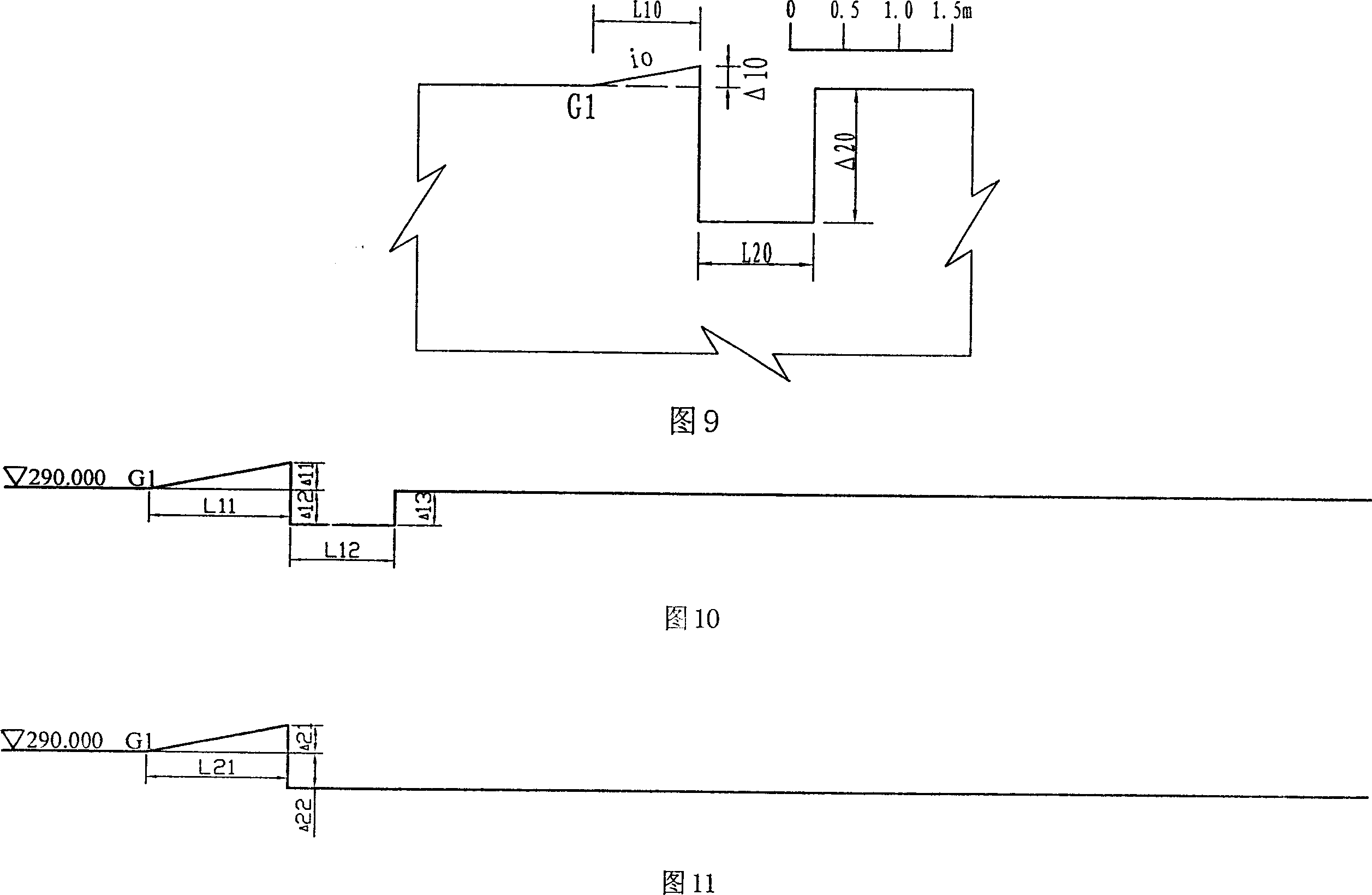
[0033] The effectiveness of the invention is verified by using several different aeration types of a 1:30 scale model of a certain project. The dimensions of the engineering prototype are shown in Figure 7, Figure 8 and Figure 9.

[0034] As shown in Figure 7, the flood discharge tunnel is a flat-bottomed flood discharge tunnel, with a rectangular pressurized section from the entrance to point F1, a rectangular pressurized outlet with a width of 5m and a height of 8m, and a rectangular open channel at the rear. The entrance roof curve (A1-B1 section) is an elliptic curve, followed by a 1:4.5 pressure plate (C1-D1 section), and the exit roof pressure plate slope is 1:4.925. The elliptic curve equation is: x 2 10 2 + y 2 6.67 2 = 1 . The points i...


PUM


Abstract

This invention relates to an aeration device of a flat-bottomed building to aerate with a combined way of raised ridge, aeration tank and a drop ridge and sets a paste ridge at the back of the tank, in which the profile line of the top of the paste ridge extends to the bottom from the top gradually along the counter flow direction in a cavity sphere, the profile line on top of the paste ridge along the current direction extends to the bottom from the top gradually at the bump section of the current and the paste ridge at the back of the cavity. Advantage: obliquity of the jet with the paste ridge is small across a ventilation tank, it's not easy to generate back flow to block the cavity, a stable cavity is formed at the flow surface of the building to reduce back flow and increase aeration efficiency, extra part is removed to improve distribution of pressure in the cavity to increase contact area of water and gas.

Description

technical field [0001] The invention relates to an aeration device for a drainage structure, in particular to an aeration device for a flat-bottom drainage structure. technical background [0002] "Deep canyons, high water heads, large flows, and lots of sediment" are the main characteristics of modern water conservancy and hydropower engineering construction. With the continuous development and utilization of water resources, countries around the world have built a large number of water conservancy projects and high dams. In 2003, 108 dams over 100m in height have been built or are under construction in my country. Among them, Ertan hyperbolic arch dam is 240m high, Xiaowan hyperbolic arch dam is 292m high, and Jinping I hyperbolic arch dam will be as high as 305m. [0003] In the construction of high dams, the investment in drainage structures accounts for about 40-60% of the entire project. When the water head reaches or exceeds 100m, its flow velocity will reach or exce...

Claims


Application Information

Patent Timeline
Patent Type & Authority Applications(China)
IPC IPC(8): E02B8/06E02B3/10
Inventor 吴建华阮仕平吴伟伟冯树荣肖峰黄张豪
Owner HOHAI UNIV
Why Eureka
Try Eureka