
Registered lamination of webs using laser cutting

A membrane and lamination layer technology, applied in the direction of lamination, lamination device, lamination auxiliary operation, etc.

Inactive Publication Date: 2007-12-26
3M INNOVATIVE PROPERTIES CO
View PDF3 Cites 14 Cited by
  • Summary
  • Abstract
  • Description
  • Claims
  • Application Information

AI Technical Summary

Problems solved by technology

If this technique is used in a grid-type circuit where the conductive traces are arranged in the vertical X and Y directions, it will result in the conductive traces having to extend to the side of the diaphragm in order to expose the conductive traces for subsequent connection. side
This limitation on the routing and access points of conductive traces can lead to limitations related to manufacturing efficiency, cost of manufacturing components, and design selectivity of circuit components and electronic devices using these components

Method used


Image

  • Registered lamination of webs using laser cutting
  • Registered lamination of webs using laser cutting
  • Registered lamination of webs using laser cutting

Examples


Embodiment Construction

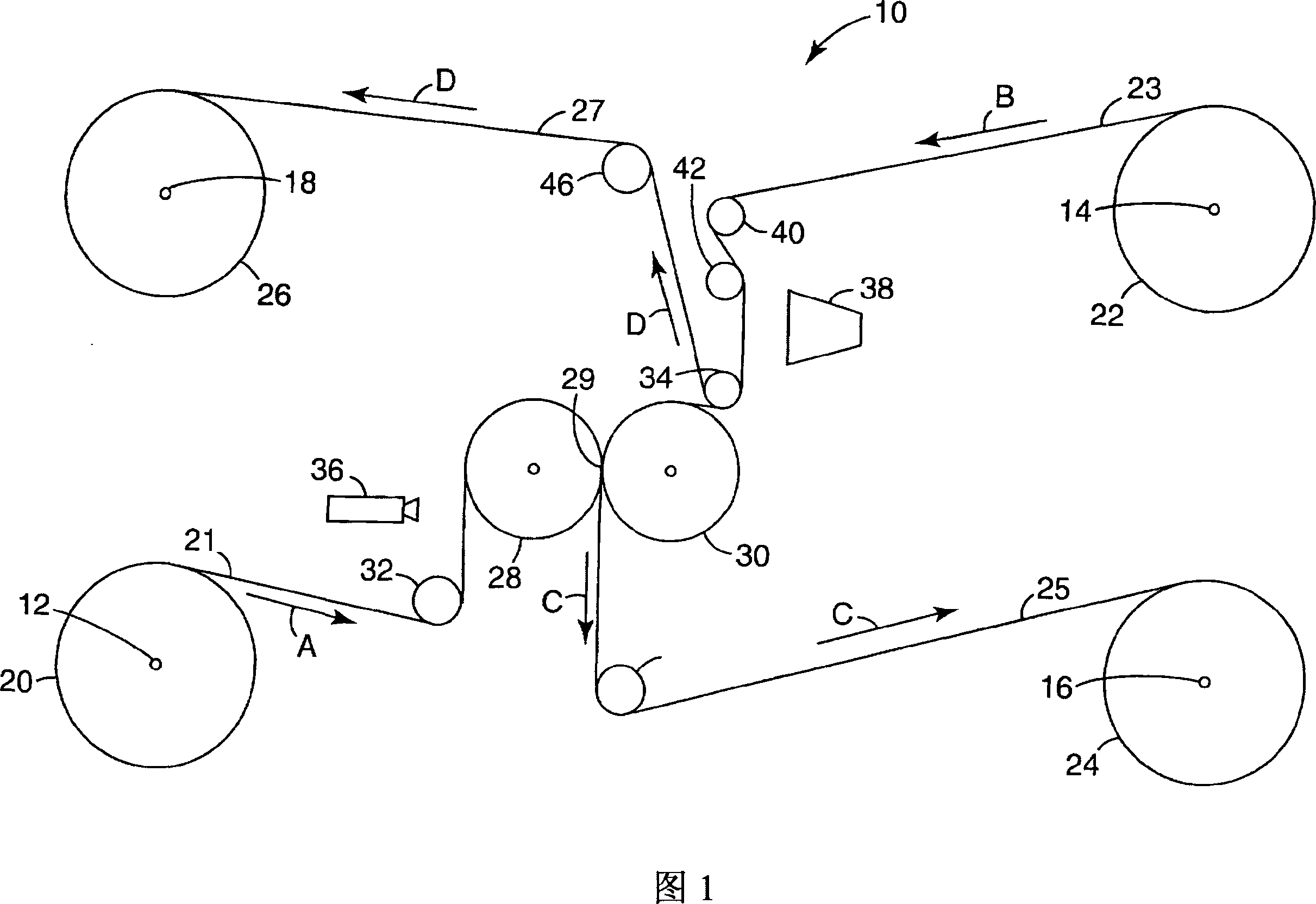
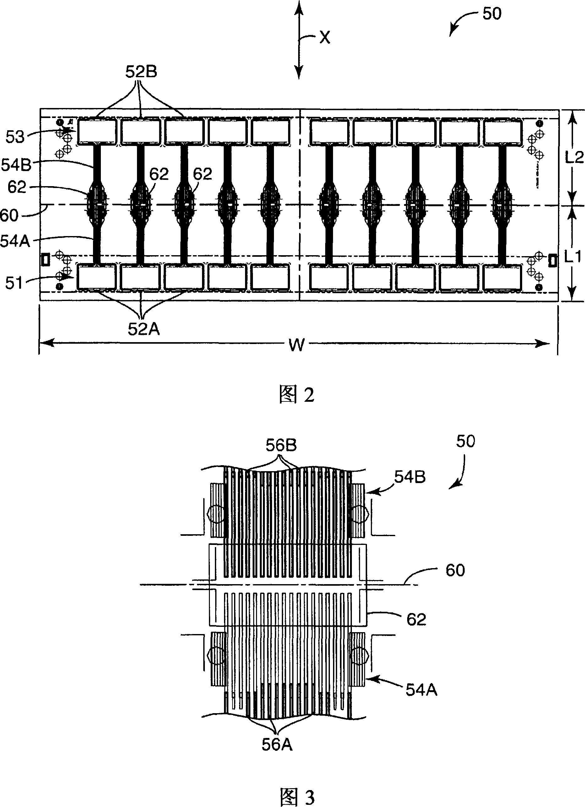
[0018] The present invention provides novel methods and apparatus that enable the formation of multilayer circuits on a membrane such that the electrical connections to the layers of the multilayer circuit can be exposed for subsequent connection to each other or to external circuits . In one aspect, the present invention provides a method for machine vision aligned cuts during lamination to expose critical areas of circuitry that would otherwise be covered by laminate layers.

[0019] The present invention also provides an efficient solution to the problem of offset that arises when attempting to manufacture multilayer circuits in the form of membranes. If the two circuit layers are formed on two separate films, each with a series of images, image shift problems can arise when the two films are laminated together in registration. This is due to the fact that the spacing between images is not maintained exactly, and any small error will cause misalignment after accumulation o...


PUM


Abstract

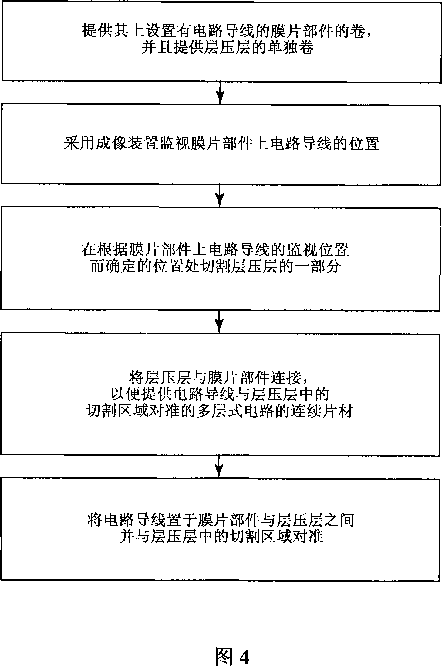
A system and method for manufacturing a multi-layered circuit assembly. The assembly includes a webbing member, a component, and a laminate layer. The method includes providing a roll of the webbing member with the component positioned thereon and a separate roll of the laminate layer, and monitoring a position of the component on the webbing member with an imaging device. The method also includes modifying a portion of the laminate layer at a location that is based on the monitored position of the component on the webbing member, and coupling the laminate layer to the webbing member to provide a continuous sheet of multi-layered circuit. The multi-layered circuit is formed with the component positioned between the webbing member and the laminate layer and aligned with the modification in the laminate layer.

Description

technical field [0001] The present invention relates generally to manufacturing processes and methods for adding layers to flexible membranes, and more particularly to the alignment of the membrane and layers and their cutting. Background technique [0002] The popularity of touch screens has increased dramatically over the past few years. In order to manufacture reliable and cost-effective high-quality touch sensors, many different technologies have been developed. Examples of touch sensor technologies include capacitive, resistive, near-field imaging (NFI), acoustic, infrared, and force sensor technologies. Common applications for touch sensors include computer monitors and mobile handheld devices such as personal digital assistants (PDAs) and tablet computers. [0003] Touch sensors often have characteristics and qualities that are unique to a particular technology. Each type of touch sensor technology imposes special requirements concerning, for example, the recogniti...

Claims


Application Information

Patent Timeline
Patent Type & Authority Applications(China)
IPC IPC(8): G06F3/033G06F3/041
CPCB32B38/1833Y10T156/1062G06F3/041B32B2457/20B32B37/12B32B37/206G06F2203/04103G02F1/13
Inventor 迈克尔·J·罗布瑞特乔治·F·扬博尔
Owner 3M INNOVATIVE PROPERTIES CO
Learn More