Frequency synthesizer

A frequency synthesizer, frequency signal technology, applied in the direction of automatic power control, electrical components, etc., can solve the problem of not preventing frequency deviation, increasing frequency error, and not preventing frequency deviation of input A/D converter level change shift and other issues to achieve the effect of improving frequency accuracy and preventing frequency offset

Active Publication Date: 2012-05-30
NIHON DEMPA KOGYO CO LTD
View PDF2 Cites 0 Cited by
  • Summary
  • Abstract
  • Description
  • Claims
  • Application Information

AI Technical Summary

Problems solved by technology

[0018] In this way, if the input level to the ADC changes greatly relative to the reference value, there will be a problem of increased frequency error
[0019] In addition, in the above-mentioned Patent Document 1, the PLL circuit actually outputs the information that the lock is released before the lock is released, but the digital phase comparator does not prevent the change of the input level to the A / D converter. frequency offset
[0020] In addition, in the above-mentioned Patent Document 2, the reproduction signal is converted into a digital signal in synchronization with the sampling clock based on the clock reproduced in the phase synchronization loop, and the clock in the sampling value corresponding to the clock pattern (clock pattern) is converted into a digital signal. Compare at least 2 sampling values ​​near the edge of the pattern, count the number of times of the same comparison result, and detect the locked state when the number is greater than or equal to the predetermined threshold, when the comparison result is reversed in the locked state, when the number of the same comparison result is greater than When it is equal to a predetermined threshold value, it is detected as an unlocked state, but this is an input signal that delays the comparison object, and this prior art does not prevent a frequency shift relative to a level change of the input A / D converter.

Method used


Image

  • Frequency synthesizer
  • Frequency synthesizer
  • Frequency synthesizer

Examples


Embodiment Construction

[0031] Embodiments of the present invention will be described with reference to the drawings.

[0032] In the frequency synthesizer according to the embodiment of the present invention, an automatic gain control circuit (AGC circuit) is provided so that the output of the AD converter becomes constant, and the correction value to the AGC circuit is used to determine the input level to the AD converter. If the correction value In the appropriate range, the AGC circuit controls the gain on the output stage of the AD converter while performing the locking (synchronization) process in the PLL control. If the value is outside the appropriate range, the AGC circuit in the PLL control Unlocked for detection, thus preventing frequency drift.

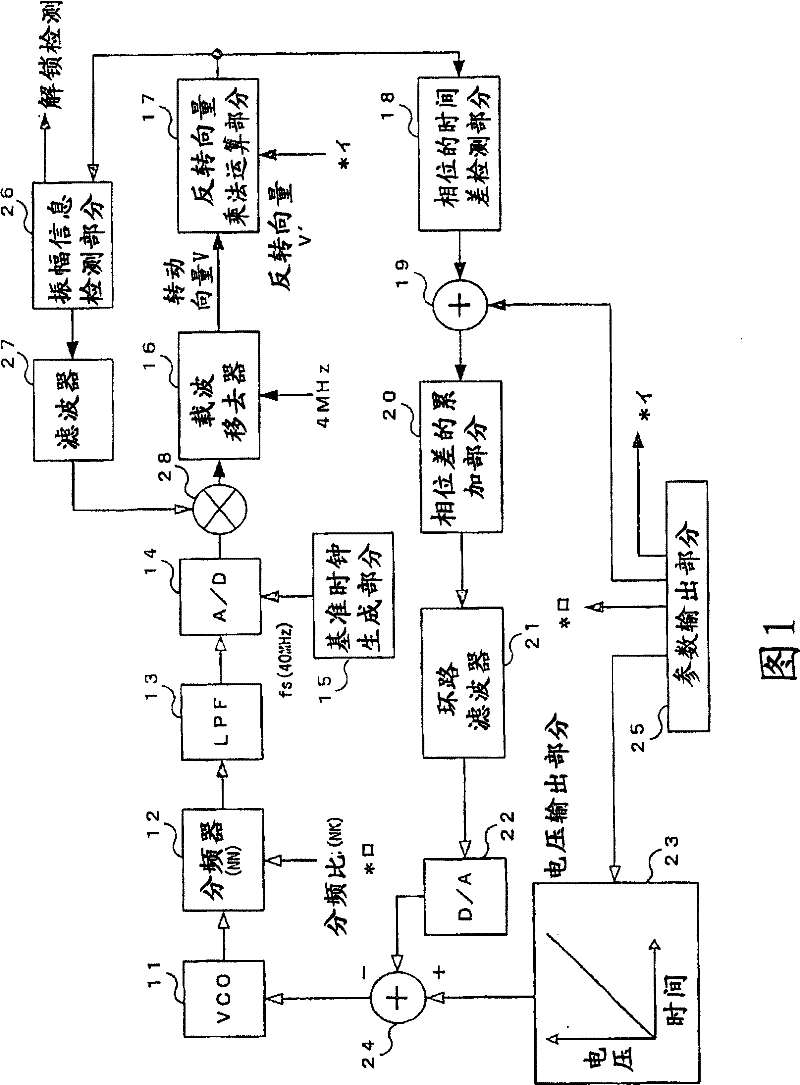
[0033] [the constitution of embodiment: figure 1 ]

[0034] refer to figure 1 A frequency synthesizer according to an embodiment of the present invention will be described. figure 1 It is a block diagram showing the configuration of the fr...


PUM


Abstract

Disclosed is a frequency synthesizer capable of preventing occurrence of a frequency shift upon occurrence of a change in the level of an input to an A / D converter by preventing PLL control from being properly operated. The frequency synthesizer includes a carrier remove (16), an inverse rotational vector multiplier (17), a phase time difference detector (18), an adder (19), a phase difference accumulator (20), a loop filter (21), a parameter output part (25), an amplitude information detector (26), a filter (27), and a multiplier (28) configured by an FPGA. Unlock detection means monitors the value of amplitude information detected by the amplitude information detector (26). When the value lies within a proper range, a lock (synchronization) process is performed under PLL control, whereas when the value is off the proper range, an unlock state in PLL control is detected.

Description

technical field [0001] The present invention relates to the frequency synthesizer (synthesizer) that can obtain the oscillating output of desired frequency, relate in particular to when the input level to AD (analog · digital) converter changes, can prevent PLL (Phase Locked Loop, phase-locked loop) ) A frequency synthesizer that controls abnormal operation and prevents frequency deviation from occurring. Background technique [0002] refer to figure 2 An existing frequency synthesizer is described. figure 2 It is a block diagram of an existing frequency synthesizer. [0003] Existing frequency synthesizers such as figure 2 As shown, it has VCO (Voltage Controlled Oscillator: Voltage Controlled Oscillator) 1; frequency divider 2; reference oscillation circuit 3; A / D (Analogue / Digital, analog / digital) converter 4; phase comparator 5; digital filter 6; D / A (Digital / Analogue, digital / analog) converter 7; analog filter 8. [0004] The VCO1 is a voltage-controlled oscillator...

Claims


Application Information

Patent Timeline
Patent Type & Authority Patents(China)
IPC IPC(8): H03L7/095
Inventor 古幡司
Owner NIHON DEMPA KOGYO CO LTD
Why Eureka
Try Eureka