Atomized spray head

A technology of atomizing nozzles and nozzles, which is applied in the directions of spray devices, spray devices, liquid spray devices, etc., can solve the problems affecting the effect of heat transfer and mass transfer, and the diffusion area of ​​atomized water flow is small, so as to achieve good atomization effect, The effect of wide diffusion area

Inactive Publication Date: 2008-01-09
CHENGDU SHENGDONG TECH
View PDF1 Cites 6 Cited by
  • Summary
  • Abstract
  • Description
  • Claims
  • Application Information

AI Technical Summary

Problems solved by technology

[0003] The authorized announcement date is January 1, 2003, and the Chinese utility model patent with the patent number ZL02215691.7 discloses a nozzle of a vertical flow cooling tower nozzle, which adopts an oval opening design, to a certain extent Th

Method used


Image

  • Atomized spray head

Examples


Example Embodiment

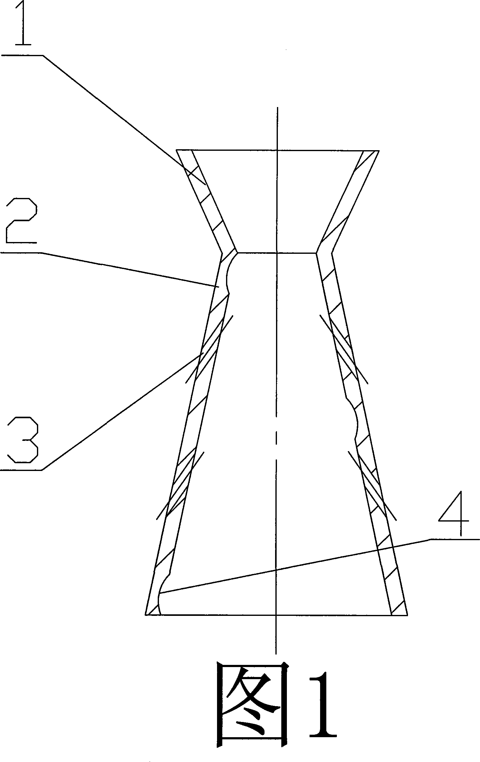
[0012] As shown in Figure 1, the present invention is a tubular whole composed of a nozzle neck 2 with a tapered inside and outside, a nozzle 1 connected to the upper end of the nozzle neck 2 and an inverted cone inside and outside. The wall of the spray neck 2 is made of A right-handed spiral groove 4 is formed on the through hole 3 inclined from the outside to the inside toward the direction of the nozzle 1 and the inner wall of the nozzle 2 , and the spiral groove 4 continuously runs through the entire inner wall of the nozzle 2 .

[0013] Of course, the present invention is not limited to the above embodiments, and the helical groove 4 may be a left-handed or right-handed helical groove 4 with at least one end and the same rotation direction.

[0014] The present invention can be obtained by processing a whole piece of iron bar material by metal machining method; also can obtain cast iron blank by casting method, and then process spiral groove 4 and through hole 3 etc. by m...


PUM


Abstract

The present invention discloses one new type of nozzle for the atomizer in industrial no-stuffing water cooling tower. The integrated tubular atomizing nozzle includes one conic nozzle neck with through holes and helical groove in the wall, and one conic spout connected to the nozzle neck. Owing to the nozzle neck with through hole and helical groove, the air through the through holes may be well mixed with water flow and the water flow produces rotating centrifugal force, reaching excellent atomizing effect.

Description

technical field [0001] The invention relates to an atomizing device for an industrial cooling water circulation cooling tower without packing, in particular to an atomizing nozzle of the atomizing device. Background technique [0002] The nozzle is an important part of the final process of the industrial cooling water circulation non-fill cooling tower atomization device. The performance of the nozzle directly determines the diameter of the cooling water atomized droplet, thereby determining the effect of heat transfer and mass transfer. [0003] The authorized announcement date is January 1, 2003, and the Chinese utility model patent with the patent number ZL02215691.7 discloses a nozzle of a vertical flow cooling tower nozzle, which adopts an oval opening design, to a certain extent The atomization effect is improved, but because the outlet hole is designed as a straight hole, it inevitably brings the disadvantage of small diffusion area of ​​the sprayed atomized water flo...

Claims


Application Information

Patent Timeline
IPC IPC(8): B05B7/02B05B1/02F28C1/00
Inventor 黄应力王骏付平
Owner CHENGDU SHENGDONG TECH
Why Eureka
Try Eureka