Board drilling machine head

A drilling machine and plate technology, which is applied in the direction of drilling machines, stone processing tools, wood processing equipment, etc., can solve the problems of poor drilling hole shape, etc., and achieve the effects of drilling stability, quality improvement, and reinforcement strength

Inactive Publication Date: 2008-01-09
苏州工业园区科特建筑装饰有限公司
View PDF0 Cites 30 Cited by
  • Summary
  • Abstract
  • Description
  • Claims
  • Application Information

AI Technical Summary

Problems solved by technology

[0004] The invention provides a head of a plate drilling machine, the purpose of which is mainly to solve the problem of poor hole shape of the head of the exist

Method used


Image

  • Board drilling machine head
  • Board drilling machine head
  • Board drilling machine head

Examples


Embodiment

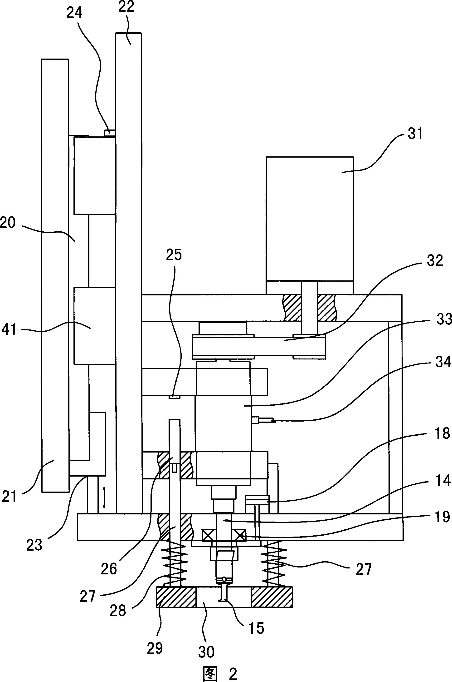
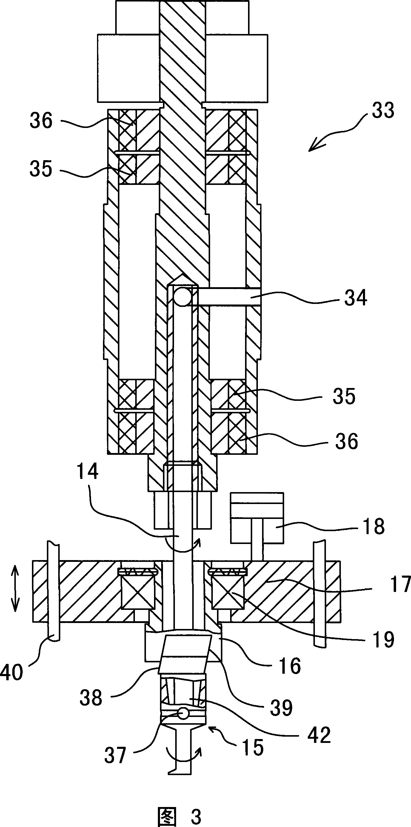
[0030] Embodiment: As shown in Fig. 2 and Fig. 3, a machine head of a plate drilling machine includes a main shaft rotation mechanism, a Z-axis feed mechanism, a cooling water supply structure and an eccentric drilling mechanism.

[0031] The eccentric drilling mechanism is mainly composed of a drill bit 15, a main shaft 14, an eccentric action block 16, a moving block 17 and a drilling cylinder 18. The shank end of the drill bit 15 is provided with a tapered counterbore 42, and the counterbore 42 is larger than the diameter of the lower end of the main shaft. The main shaft 14 The lower end of the drill bit stretches into the counterbore 42, and is hinged with the drill bit 15 through the pin 37 in the middle section (seeing figure 3), so that the drill bit 15 can swing and deflect relative to the main shaft 14, that is, the drill bit 15 can still swing with the hinged point as the base point. The tail of the drill bit 15 is provided with a pair of first inclined surfaces 38 (...


PUM


Abstract

The plate drilling machine head includes one main shaft rotating mechanism, one Z-axis feeding mechanism, one cooling water providing mechanism, and one eccentric reaming mechanism. The eccentric reaming mechanism comprises one bit with one pair of first bevels in the tail for controlling its swing, one main shaft with lower end hinged to the middle section of the bit for swinging the bit, one eccentric block with one pair of second bevels to slide fit the first bevels, one shifting block capable of shifting in Z direction, and one reaming stroke acting unit acting on the shifting block in Z direction. The present invention has high quality of drilled hole.

Description

technical field [0001] The invention relates to a plate drilling machine for back-cut anchoring wall decoration panels, in particular to a machine head used for drilling on the plate drilling machine. Background technique [0002] With the development of the building decoration industry, the appearance of urban buildings is not only the pursuit of shape, more buildings begin to pay attention to the beauty, practicality and environmental protection of the exterior wall decoration, so curtain wall panels are adopted by more and more construction companies . At present, the curtain walls of urban buildings mostly use decorative plates such as slate, ceramic plates or microcrystalline slabs, and the fixing methods are mostly back-cut anchoring installations. Back-cut anchor installation needs to drill blind holes on the back of the decorative panel, so that the panel can be suspended and installed on the exterior wall of the building with back-cut anchor bolts and L-shaped anch...

Claims


Application Information

Patent Timeline
IPC IPC(8): B28D1/14B27C3/00
Inventor 吴斌陆锋
Owner 苏州工业园区科特建筑装饰有限公司
Why Eureka
Try Eureka