Display controller in display device, and method of transferring display data

A technology for displaying controllers and displaying data, applied to static indicators, cathode ray tube indicators, instruments, etc., can solve the problems of impossible display of QVGA, etc., achieve easy large screen size, solve the number of pixels, and solve the effect of increasing

Inactive Publication Date: 2008-01-09
RENESAS ELECTRONICS CORP
View PDF1 Cites 5 Cited by
  • Summary
  • Abstract
  • Description
  • Claims
  • Application Information

AI Technical Summary

Problems solved by technology

In this case, it is impossible to display an image of QVGA size (240×320=76800 pixels)

Method used


Image

  • Display controller in display device, and method of transferring display data
  • Display controller in display device, and method of transferring display data
  • Display controller in display device, and method of transferring display data

Examples


Embodiment Construction

[0045] Now, the invention will be described herein with reference to illustrative embodiments. Those skilled in the art will recognize that many alternative embodiments can be accomplished using the teachings of the present invention and that the invention is not limited to the embodiments shown for explanatory purposed.

[0046] A display device, a display controller, and a method of transmitting display data according to embodiments of the present invention will be described below with reference to the accompanying drawings. In this embodiment, a dot-matrix type liquid crystal display device is taken as an example of a display device.

[0047] 1 Overview

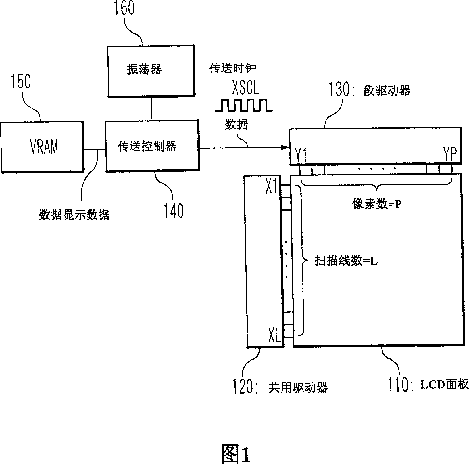
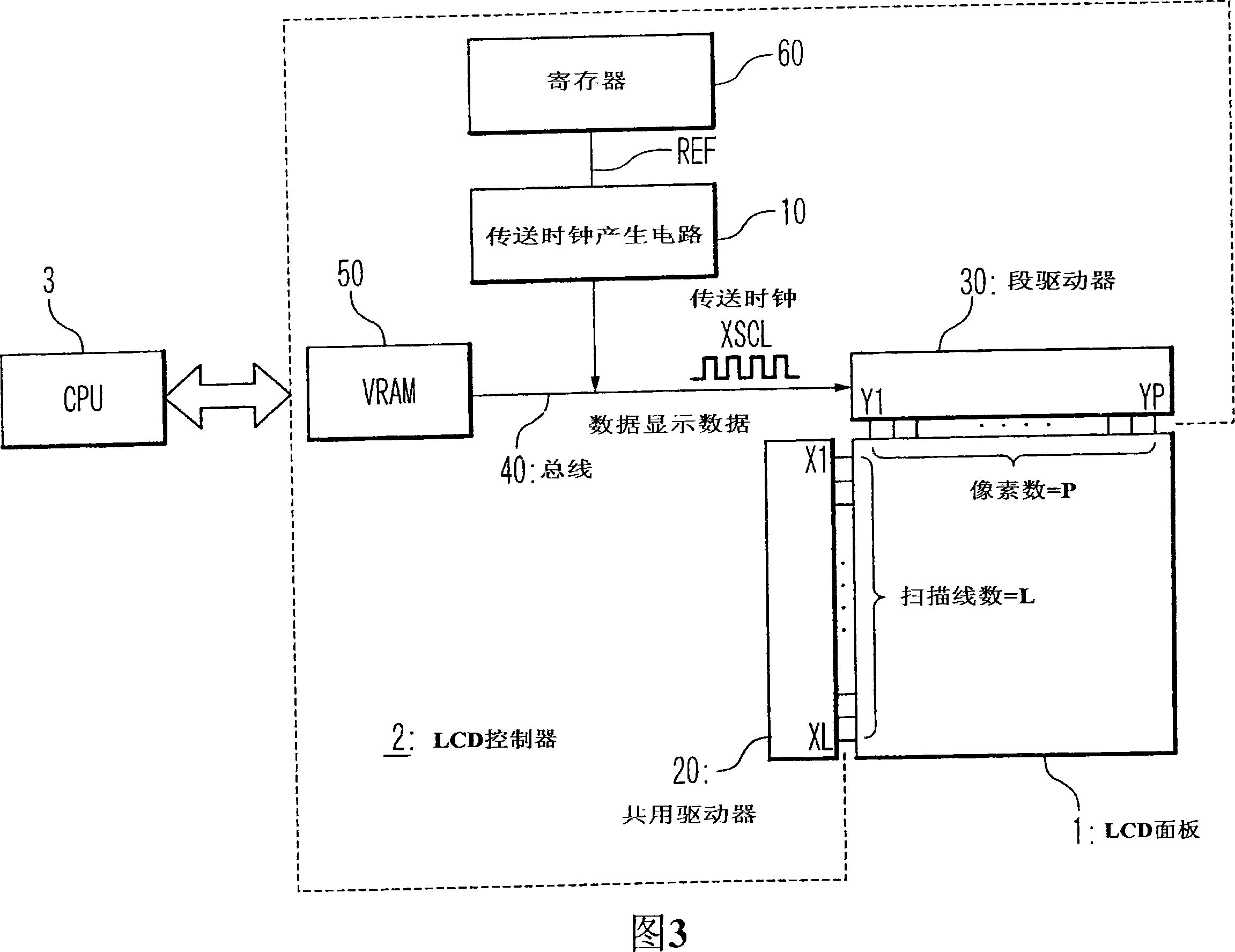
[0048] FIG. 3 schematically shows the structure of a dot matrix type liquid crystal display device according to this embodiment. In FIG. 3 , the liquid crystal display device has an LCD panel 1 , an LCD controller 2 and a CPU 3 . The LCD controller 2 controls image display on the LCD panel 1 . CPU 3 transmits various d...


PUM


Abstract

A display controller comprising: a memory in which a display data is stored; a driver configured to drive a display panel in response to the display data; and a clock generation circuit configured to generate a clock that is used for transferring the display data from the memory to the driver. The generated clock is fed back to adjust a clock frequency of the clock.

Description

technical field [0001] The present invention relates to display devices. In particular, the present invention relates to a technique for controlling display data transfer in a display device. Background technique [0002] A liquid crystal display device having a VRAM (Video RAM) in which display data is stored is known (for example, see Japanese Laid-Open Patent Application JP Kokai Hei 10-97226). In such a liquid crystal display device, it is necessary to transfer display data from a VRAM to a segment driver. [0003] FIG. 1 schematically shows the structure of a typical liquid crystal display device with VRAM. This liquid crystal display device has an LCD (Liquid Crystal Display) panel 110 , a common driver 120 and a segment driver 130 . The LCD panel 130 has L×P pixels (L and P are natural numbers) arranged in a matrix. These pixels are formed at intersections of L scan lines X1 to XL extending in the row direction and P data lines Y1 to YP extending in the column dir...

Claims


Application Information

Patent Timeline
Patent Type & Authority Applications(China)
IPC IPC(8): G09G3/36
CPCG09G3/3648G09G5/395G09G2310/08
Inventor 冈村哲
Owner RENESAS ELECTRONICS CORP
Why Eureka
Try Eureka