Drive device for electric vehicle

Inactive Publication Date: 2015-11-18
HITACHI AUTOMOTIVE SYST LTD
View PDF6 Cites 2 Cited by
  • Summary
  • Abstract
  • Description
  • Claims
  • Application Information

AI Technical Summary

Problems solved by technology

[0003] In the structure of the existing motor power unit described in Patent Document 1, because the length of the front and rear direction of the motor power unit is large, when the motor power unit is mounted, the space occupied in the front and rear direction of the motor chamber is large, and not only the space The utilization rate is low, and there is also the problem that the layout of other equipped equipment is restricted

Method used


Image

  • Drive device for electric vehicle
  • Drive device for electric vehicle
  • Drive device for electric vehicle

Examples


Embodiment Construction

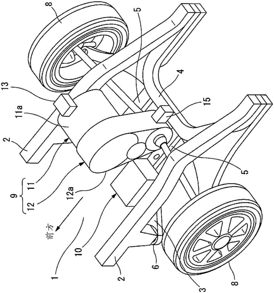
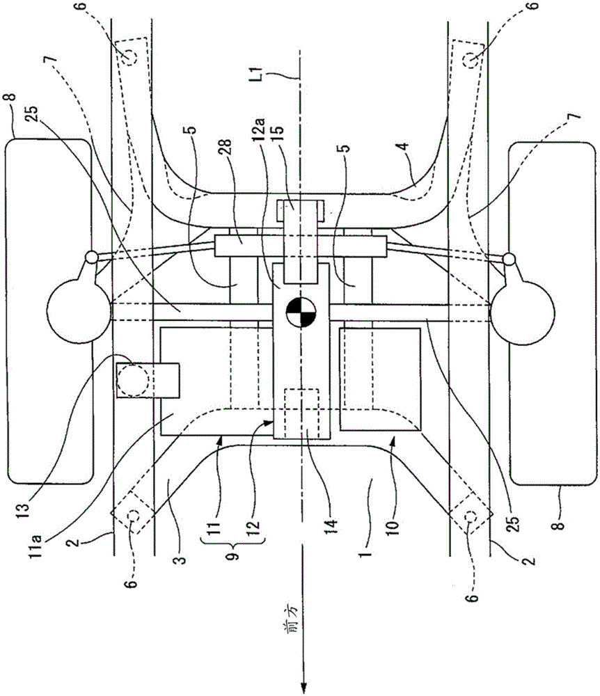
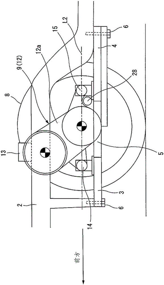
[0017] Figure 1 to Figure 5 A more specific first embodiment of the drive device for an electric vehicle for carrying out the present invention is shown, in particular, figure 1 It shows the schematic layout of the electric motor power unit as the driving device in the electric motor room of the front-wheel-drive electric vehicle. in addition, figure 2 yes figure 1 top view illustration of figure 2 yes figure 1 The side view explanatory drawing of , in addition, image 3 means from figure 1 An explanatory diagram of the front view of the front view.

[0018] remove figure 1 other than Figure 2 ~ Figure 4 As shown, in the motor room 1 at the front of the vehicle body, a pair of left and right side members 2 as strength members extending in parallel to the front of the vehicle and forming the skeleton of the motor room 1, as shown in FIG. figure 2 As shown, a pair of suspension members 3 and 4 independent in front and rear are arranged on the lower side of the pair...


PUM


Abstract

A motor power unit (9) is arranged inside a motor room (1). The motor power unit (9) is formed by integrally joining a motor (11) and a speed reducer (12), which houses a speed reduction gear and a differential gear inside a speed reducer case (12a), by employing the end surface of a motor case (11a) on the rotary shaft side as the joining surface. The motor (11) is located above the differential gear which is housed inside the speed reducer case (12a). Further, the rotary shaft of the motor (11) is located more toward the vehicle front side than the center of rotation of the differential gear. With this structure, the length of the motor power unit (9) in the front-to-rear direction can be shortened.

Description

technical field [0001] The invention relates to a drive device as a power unit of an electric vehicle. Background technique [0002] In a front-wheel-drive electric vehicle using an electric motor as a power machine, for example, as described in Patent Document 1, an electric motor and a speed reducer are combined to form a motor power unit, and the electric motor power unit is arranged in a motor room instead of an engine room of a gasoline engine vehicle. . That is, a differential gear is accommodated in the above-mentioned speed reducer as a final drive gear that decelerates the rotational force of the electric motor and distributes it to the left and right wheels. Therefore, the electric motor and speed reducer aligned in the vehicle width direction are integrated Combined to form a motor power unit, the motor power unit is arranged in the motor room so that the rotation center of the above-mentioned differential gear is oriented in the vehicle width direction. In addi...

Claims


Application Information

Patent Timeline
Patent Type & Authority Applications(China)
IPC IPC(8): B60K1/00B60K17/04B60K17/16
CPCB60K1/00B60K2001/001B60K17/165B60L15/007B62D9/002
Inventor 山本立行高桥明
Owner HITACHI AUTOMOTIVE SYST LTD
Why Eureka
Try Eureka