LED module

A technology of light-emitting diodes and modules, applied in the direction of electrical components, electric solid-state devices, circuits, etc., can solve problems that affect the luminous efficiency of light-emitting diode grains 22, cannot meet the requirements of light-emitting diode modules 10, and general products have no structure, etc., to achieve Ensuring luminous quality, reducing steps and time, and the effect of technological progress

Inactive Publication Date: 2008-01-09
GIGNO TECH CO LTD
View PDF0 Cites 8 Cited by
  • Summary
  • Abstract
  • Description
  • Claims
  • Application Information

AI Technical Summary

Problems solved by technology

If the temperature of the LED element 20 is not immediately assisted, it will affect the luminous efficiency of the LED grain 22, and even shorten its service life.
In the prior art, the heat energy generated by each LED die 22 can only be conducted from the bump 221 to the carrier board S through the lead frame 23 in the same way as the electrical connection, and there is no other heat dissipation path, so Obviously can't meet the requirement of having LED module 10
[0009] It can be seen that the above-mentioned existing light-emitting diode modules obviously still have inconvenience and defects in structure and use, and need to be further improved urgently.
In order to solve the above-mentioned problems, the relevant manufacturers have tried their best to find a solution, but no suitable design has been developed for a long time, and the general products do not have a suitable structure to solve the above-mentioned problems. This is obviously related. The problem that the industry is eager to solve

Method used


Image

  • LED module
  • LED module
  • LED module

Examples


no. 1 example

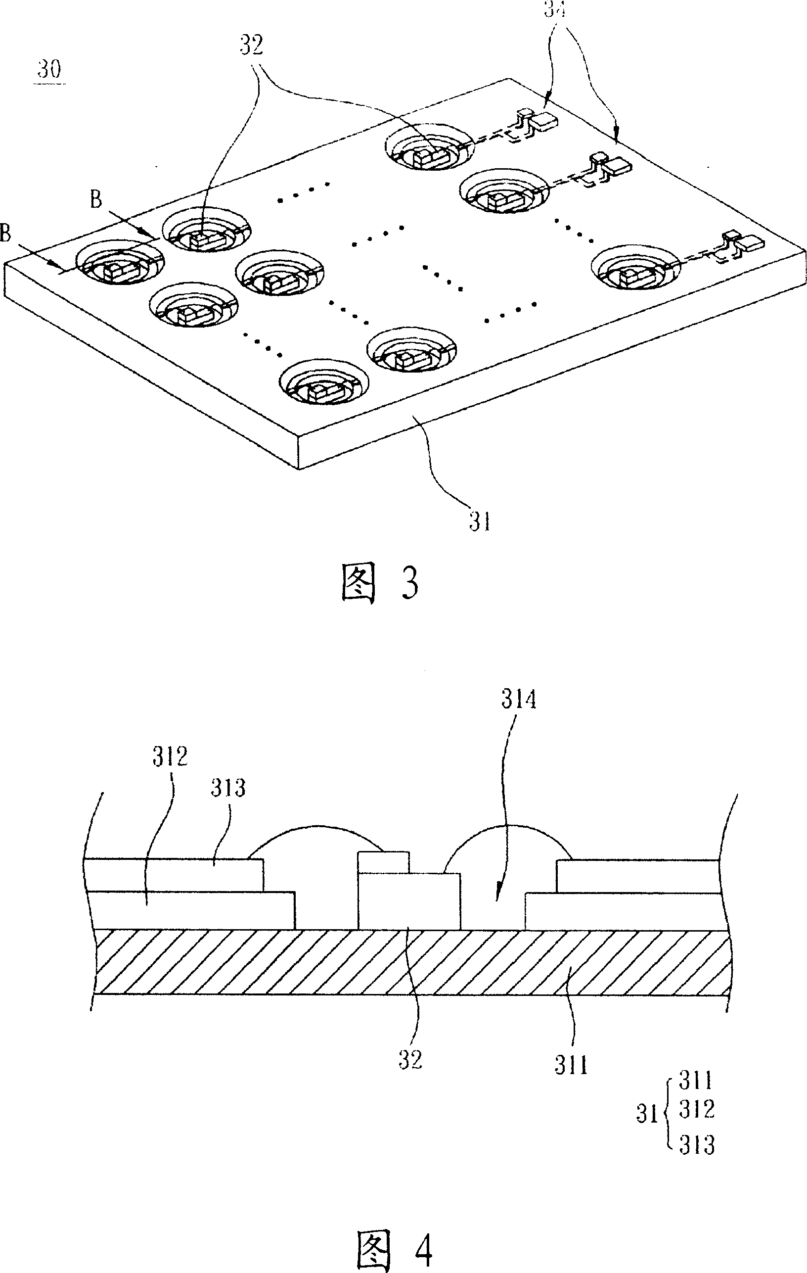
[0092] First, please refer to FIG. 3 to FIG. 10 to illustrate the first embodiment of the LED module of the present invention.

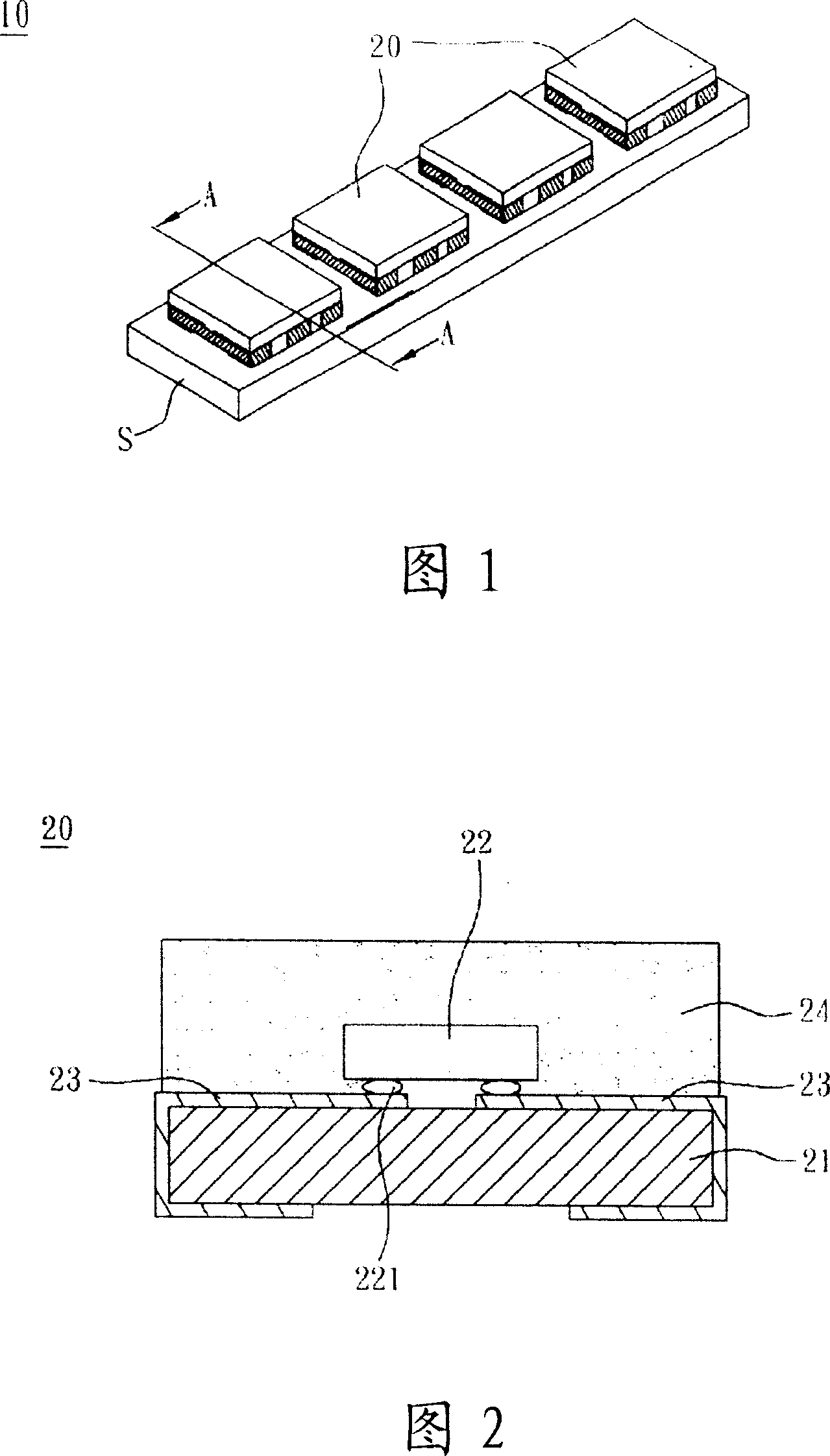
[0093] Please refer to FIG. 3 , which is a three-dimensional schematic view of the LED module according to the first embodiment of the present invention. The LED module 30 includes a metal circuit substrate 31 and a plurality of LED chips 32 . It should be noted that the number and arrangement of the LED chips 32 in the LED module 30 are not limited. In this embodiment, the light emitting diode dies 32 are arranged in an array as an example, of course, each light emitting diode die 32 may also be arranged in a straight line.

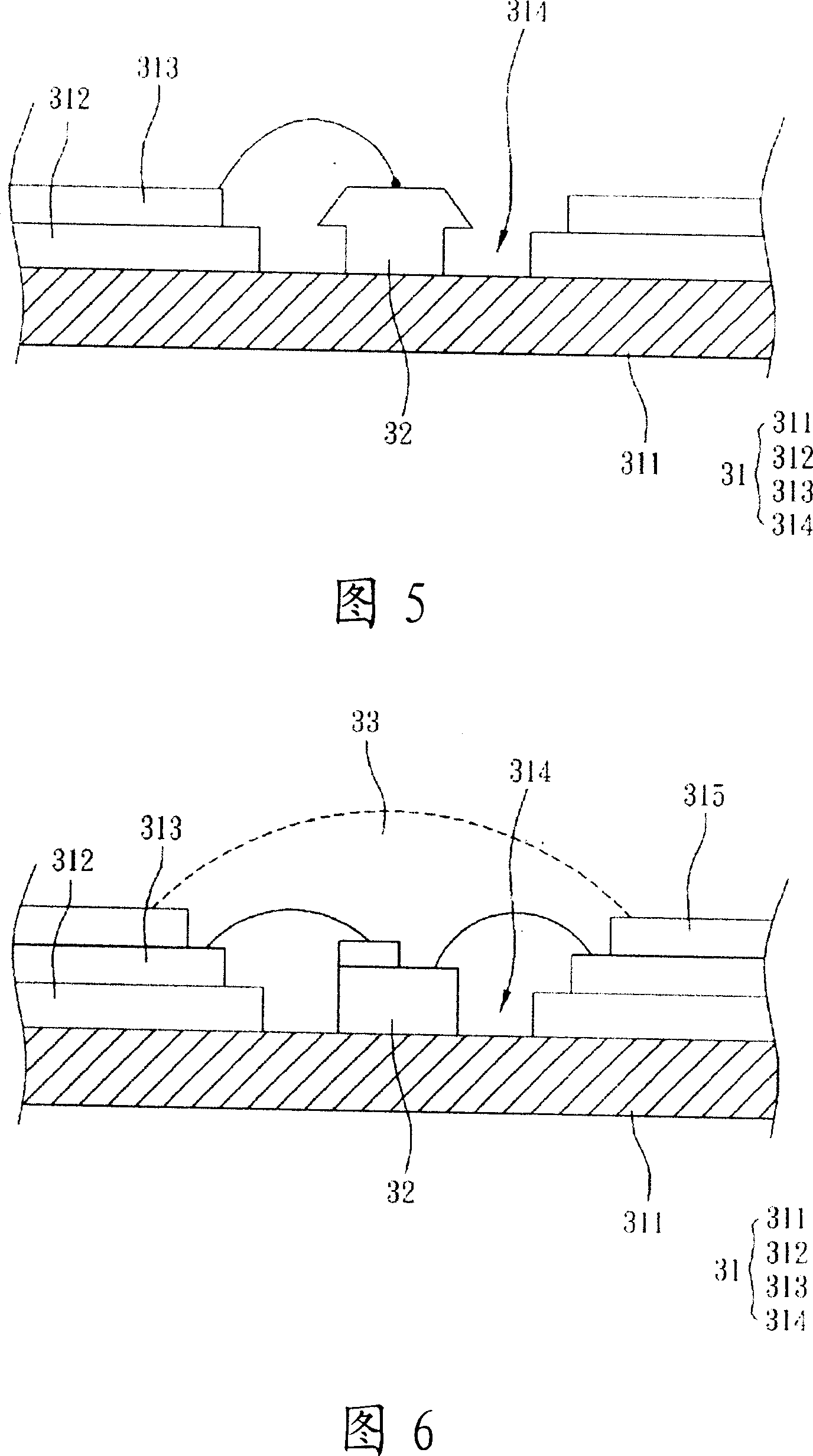
[0094] Please refer to FIG. 3 and FIG. 4 at the same time, wherein FIG. 4 is a schematic cross-sectional view of the light-emitting diode module according to the first embodiment of the present invention along the B-B section in FIG. link relationship. The metal circuit substrate 31 sequentially includes a metal plate body 3...

no. 2 example

[0106] Next, please refer to FIG. 12 to FIG. 18 to illustrate the second embodiment of the LED module of the present invention.

[0107] Please refer to FIG. 12 , which is a schematic view of the LED module according to the second embodiment of the present invention. The LED module 40 includes a metal circuit substrate 41 and a plurality of LED elements 42 . Wherein, the metal circuit substrate 41 has the same technical features and functions as the metal circuit substrate 31 in the first embodiment, so it will not be repeated here.

[0108] The LED module 40 can further include a driving circuit 44 . The driving circuit 44 is disposed on the metal circuit substrate 41 and electrically connected to each LED element 42 to drive the LED elements 42 . Wherein, the driving circuit 44 has the same technical features and functions as the driving circuit 34 in the first embodiment, so it will not be repeated here.

[0109] Please refer to FIG. 12 and FIG. 13 at the same time. FIG. ...


PUM


Abstract

The invention is concerned with the light-emitting diode module group, includes the metal circuit board and the complex number of light-emitting diode grain. The metal circuit board includes the metal plate, the first dielectric layer and the circuitry layer orderly; the first dielectric layer is with the complex number of hatch; where the light - emitting diode grain set on and they connects with the circuitry layer by electricity. The invention resolves the problem of thermolysis that prolongs the light-emitting diode module group life cycle and ensures the quality of the production by reinsuring the process of the heat energy generating of the light-emitting diode grain can be transmitted to the circuitry layer or the metal plate through the base board directly that reduces the temperature of the light-emitting diode component.

Description

technical field [0001] The invention relates to a light-emitting module, in particular to a light-emitting diode crystal grain of the light-emitting diode module can be directly in contact with a metal plate body, which can quickly transfer heat energy, and prolong the service life and luminous quality of the light-emitting diode module. Reduce the steps and time of the packaging process and assembly process, and can truly solve the problem of heat dissipation of the light-emitting diode module. Background technique [0002] A light-emitting diode is a light-emitting element made of semiconductor materials. The element has two electrode terminals. A voltage is applied between the terminals, and a very small voltage is passed through. Through the combination of electron holes, the remaining energy can be excited in the form of light. released. [0003] Different from ordinary incandescent light bulbs, light-emitting diodes are cold-emitting, which have the advantages of low ...

Claims


Application Information

Patent Timeline
IPC IPC(8): H01L25/00H01L25/075H01L23/36
CPCH01L2224/16225H01L2224/48091H01L2224/48247H01L2224/49107H01L2224/73265H01L2924/00014
Inventor 林峰立
Owner GIGNO TECH CO LTD
Why Eureka
Try Eureka