Radspanner

A wheel tensioner and tensioner technology, applied in the direction of overhead lines, can solve problems such as braking and unevenness, and achieve the effects of high mechanical stability and cheap manufacturing

Active Publication Date: 2008-01-16
理查德伯格电子装置有限及两合公司
View PDF5 Cites 8 Cited by
  • Summary
  • Abstract
  • Description
  • Claims
  • Application Information

AI Technical Summary

Problems solved by technology

However, this can also lead to uneven braking of the subsequent tensioned weight

Method used


Image

  • Radspanner
  • Radspanner
  • Radspanner

Examples


Embodiment Construction

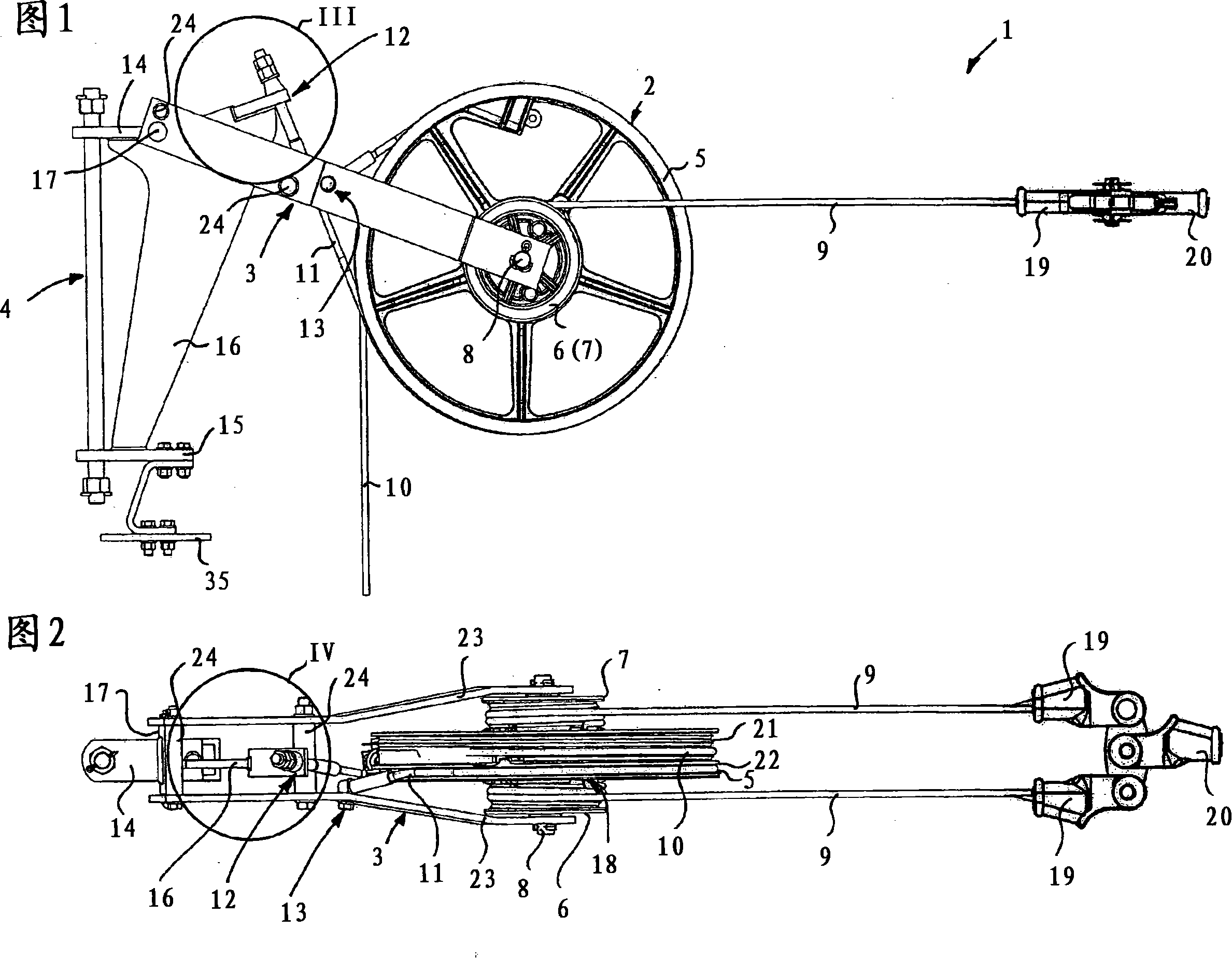
[0044] Figure 1 shows a side view of the wheel tensioner of the present invention in operation. The wheel tensioner 1 basically comprises a tensioning wheel 2 which is connected via a pivot arm 3 to a fastening device 4 . A tensioning wheel 2 in the form of a spoked wheel has a larger roller 5 and smaller rollers 6, 7 (see FIG. 2 ) arranged on either side of said larger roller, resulting in a symmetrical configuration of the tensioning wheel 2 . The rollers 5 , 6 , 7 are mounted rotatably on a common hub 8 held by the pivot arm 3 .

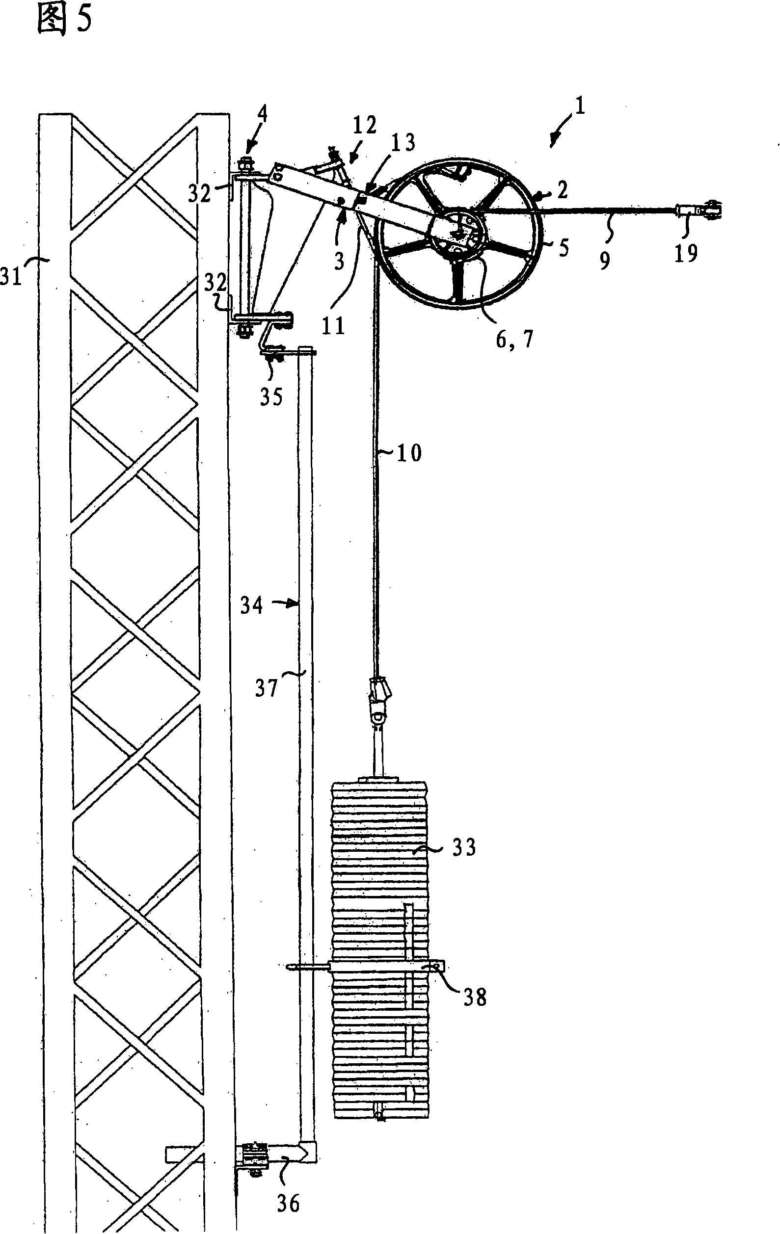
[0045] A tensioning rope 9 is wound on the two tensioning drums 6 , 7 . The larger brake drum 5 carries the weight rope 10 for the subsequent tensioning weight 33 shown in FIG. 5 . The weight rope 10 is wound multiple times around the brake drum to increase the applied gravitational force. The brake drum 5 also carries a brake cable 11 , which is fastened at an upper fastening point 12 to the fastening device 4 and at its lower fastening point...


PUM


Abstract

The present invention relates to a wheel tensioner (1) for sliding contact line or bearing rope of a trackless device. The wheel is arranged with a stop with an arrester and a holding device used when the sliding contact line or the bearing rope ruptures. Thus, the wheel tensioner comprises a tensioner pulley (2) which is fixed on the trackless bracket or a wall by means of a fixed device (4) and can swing relative to the trackless bracket or the wall vertically; the tensioner pulley is arranged with a braking roller (5) for installing braking belt or braking rope (11). The braking rope is fixed on the fixed device (4) at the upper fixing point (12). The wheel tensioner also comprises a swing arm (3) which supports the tensioner pulley (2) and is supported on the fixed device (4) by means of the swing of a rotary bearing (17). The braking rope (11) is fixed on the swing arm (3) at the lower fixing point (13).

Description

technical field [0001] The invention relates to a wheel tensioner. Background technique [0002] The conductor lines and the carrying cables of the trackless system must be constantly tensioned with a certain tensile force, independent of the weather, in order to ensure the correct operation of the trackless system. Tensioning devices with pulley tensioners are used to tension trolley lines and carrying ropes. The wheel tensioners are fastened at regular intervals to a trackless support or wall by means of a fastening device and are part of a holding device supporting the trackless installation. Each wheel tensioner has a tensioning drum, on which a tensioning rope connected to the trackless device is wound. The tensioning of the tensioning rope takes place via a subsequent tensioning weight suspended on the tensioning drum from the weighting rope. The subsequent tensioning weight is designed in such a way that, in particular, temperature-induced length changes of the tra...

Claims


Application Information

Patent Timeline
Patent Type & Authority Applications(China)
IPC IPC(8): B60M1/26
CPCB60M1/26
Inventor H·利加尔
Owner 理查德伯格电子装置有限及两合公司
Why Eureka
Try Eureka