Pressing-drawing-type chain pulley transmission variable speed gear and pedal type step bicycle

A technology of pressing and zipping chains and shifting devices, which is applied in the directions of bicycles, motor vehicles, and vehicle parts, can solve the problems of high manufacturing cost, poor reliability, complicated structure, etc., and achieve the effect of increasing lung capacity and enhancing coordination ability.

Inactive Publication Date: 2008-01-16
陈燕
View PDF1 Cites 2 Cited by
  • Summary
  • Abstract
  • Description
  • Claims
  • Application Information

AI Technical Summary

Problems solved by technology

[0006] The purpose of the present invention is to overcome the defects of the above-mentioned prior art that the structure is complicated, the manufacturing cost is high, the stability and reliability are poor, and the rear wheel cannot be reversed, and a kind of pressur

Method used


Image

  • Pressing-drawing-type chain pulley transmission variable speed gear and pedal type step bicycle
  • Pressing-drawing-type chain pulley transmission variable speed gear and pedal type step bicycle
  • Pressing-drawing-type chain pulley transmission variable speed gear and pedal type step bicycle

Examples


Embodiment 1

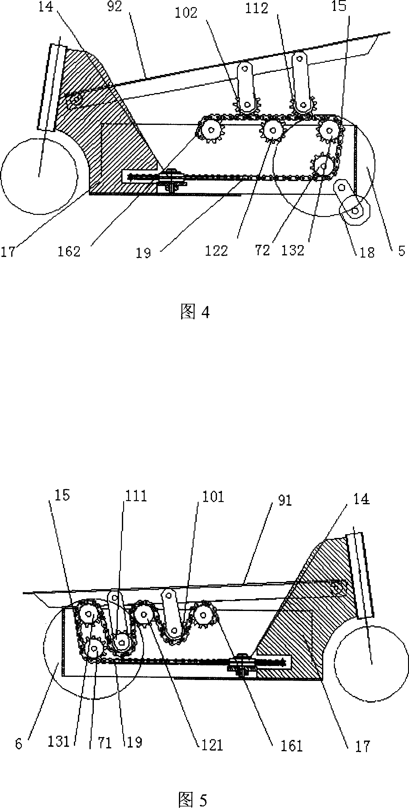
[0030] As shown in Figures 4 and 5, a compression-pull chain pulley transmission speed change device includes two sets of symmetrically arranged chain pulley speed change assemblies, a vertical sprocket 14, a speed change assembly with the two sets of chain pulleys and the The chain 15 matched with the vertical sprocket 14 is connected with a chain cross joint 19, 19 (left and right sides) between the vertical sprocket 14 and each group of chain pulley shift components.

[0031] Two sets of symmetrically arranged chain pulley shift components: one set is two left driving chain pulleys 101, 111, two left driven chain pulleys 121, 131 arranged alternately with the two left driving chain pulleys 101, 111, and one fixed The sprocket 161 (which is fixed and non-rotating, the left end of the chain 15 is fixed on the fixed sprocket 161) and a left one-way ratchet flywheel 71; the other group is two right drive chain pulleys 102, 112, three Two right driven chain pulleys 122, 132 arranged...

Embodiment 2

[0036] The difference between the second embodiment and the first embodiment is that each chain pulley is replaced by a steel rope pulley, and the one-way ratchet flywheel is replaced by a steel rope flywheel, which is connected by a steel rope, which can achieve less driving force requirements The compression pull type steel rope pulley shifts, in addition, the above-mentioned chain cross joint 19 is also omitted.

[0037] The positions and connection relations of the components of the second embodiment and the first embodiment are the same, and will not be repeated here.

Embodiment 3

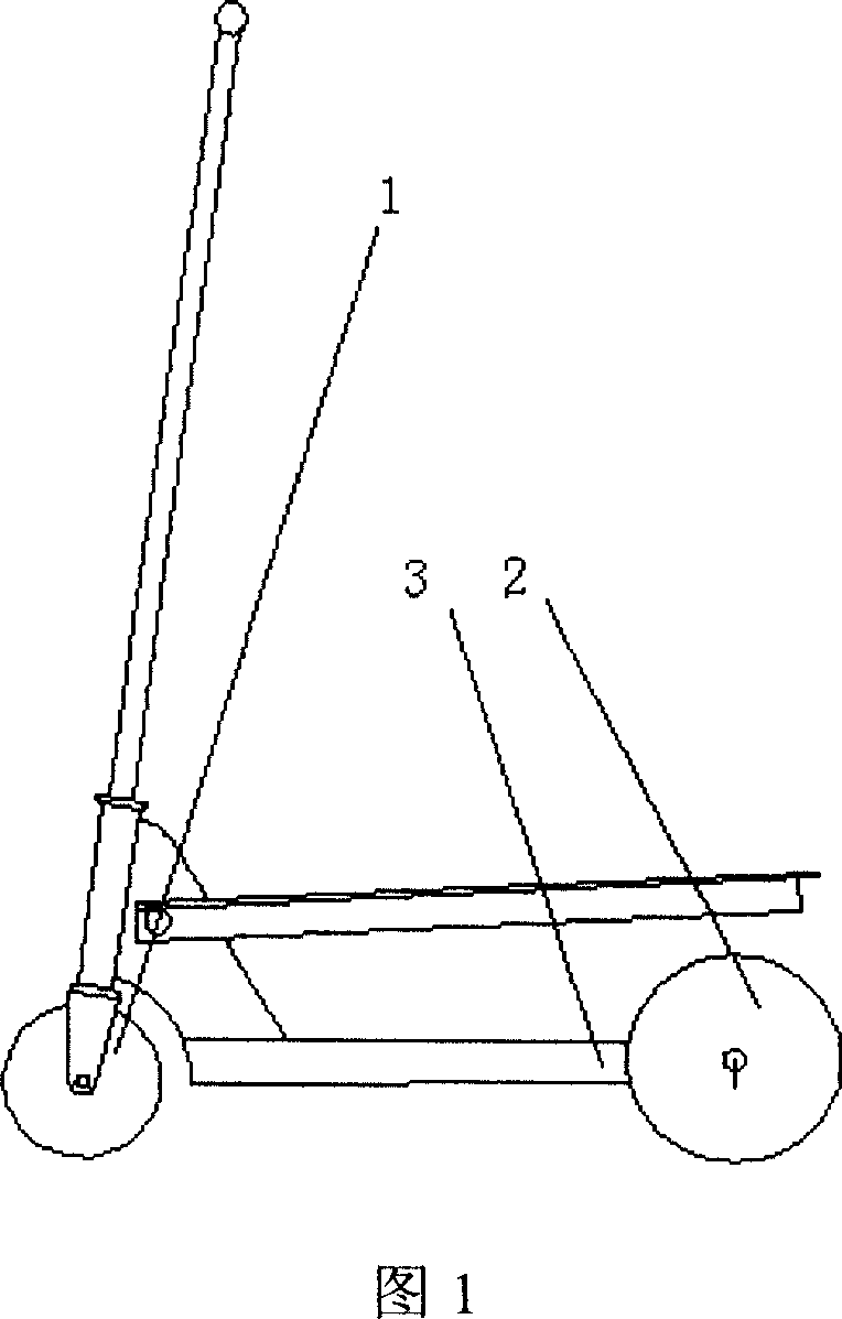
[0039] As shown in Figure 1 to Figure 7, a pedal-type stepping bicycle is a kind of pedaling with two pendulum pedals alternately, pressing and pulling the chain and accelerating the rotation of the one-way ratchet flywheel to make the wheel move forward continuously. It accelerates while driving, and realizes a differential device in which one pedal goes down and the other pedal automatically goes up.

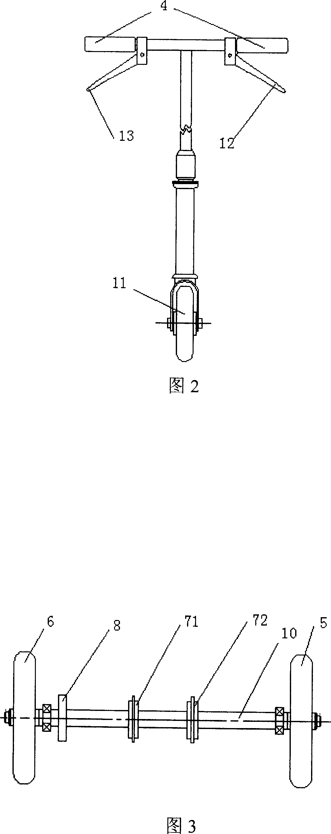
[0040] The pedal-type stepping bicycle includes a front wheel part 1, a rear wheel part 2, and a frame part 3 connected between the front wheel part 1 and the rear wheel part 2. The frame part 3 includes a correspondingly set up and down swing The left and right pedals 91, 92 and the pressure-pull sprocket gear transmission device connected with the left and right pedals 91, 92, the rear wheel component 2 includes a differential coaxially correspondingly arranged driving rear wheel 5, a differential The driving rear wheel 6 and a reversing small wheel 18 installed inside the drivi...


PUM


Abstract

The invention discloses a tension-compression gipsy sheave drive gear change device, consisting of two gipsy sheave components which are symmetrically arranged, a vertical chain wheel, a chain matching with the two gipsy sheave gear change components and the vertical chain wheel. A cross tie-in of the chain is connected with the vertical chain wheel and each gipsy sheave gear change components group. The invention also discloses a pedal step bike which consists of front wheel assembly, rear wheel assembly and bicycle frame assembly. The bicycle frame assembly is equipped with the tension-compression gipsy sheave drive gear change device. The rear wheel assembly is provided with a drive rear wheel and a differential rear wheel which are differentially arranged on the same shaft. The gipsy sheave gear change device actualizes the effects of one mechanism, multipurpose, reliability of the products performance, compact structure, light weight, high quality, high efficiency and low cost, thus the invention is suitable to be produced in for mass production. The pedal step bike can be used for fun, amusement and safety, and be used in, short-distance riding instead of walking and as well as in body building, therefore, the invention is a practical, a novel product for riding instead of walking and body building.

Description

Technical field [0001] The invention relates to a pressure-pull type chain pulley transmission speed change device and a pedal type stepping bicycle equipped with a pressure-pull type chain pulley transmission speed change device. Background technique [0002] At present, the power transmission device of scooter generally adopts crank, connecting rod, rack, chain and gear transmission. The speed change mechanism generally adopts gears and sprockets to accelerate. The structure of these institutions is complicated and heavy, and the production and installation precision is high, and the manufacturing cost is high. Mass production and product commercialization are not suitable. [0003] A self-powered scooter with the application number 200510021759.9. The scooter uses a cable to transmit power, and the large and small wire wheel group (pulley group) realizes speed change. Although this mechanism is better than the above, due to insufficient cable rigidity, the cable is easily stre...

Claims


Application Information

Patent Timeline
IPC IPC(8): B62M1/04B62K17/00B62M1/24
Inventor 陆德昌
Owner 陈燕
Why Eureka
Try Eureka