
Valve hydraulic driver

A hydraulic driver and driver technology, applied to valve details, valve devices, engine components, etc., can solve problems such as slow response speed, difficult motor performance, and influence on opening performance

Inactive Publication Date: 2008-01-16
JIANGSU ZHONGAO CONTROL SYST TECH
View PDF0 Cites 0 Cited by
  • Summary
  • Abstract
  • Description
  • Claims
  • Application Information

AI Technical Summary

Problems solved by technology

[0003] At present, there are two main structural types of hydraulic drive devices for valves, especially for butterfly valves, ball valves and other shut-off valves: one is to use a hydraulic motor to directly drive the valve stem to rotate to realize the opening and closing of the valve. The control operation type has high cost and heavy weight, and it is difficult to fully exert the motor performance, which is especially prominent for multi-valve systems that require centralized control or remote control; the other is the piston rack structure, which is through the piston rack. To drive the gear and valve stem to realize the opening and closing of the valve, this structural type not only has high cost and complex structure, but also has relatively slow response speed, and the opening performance is affected by the transmission quality of the gear and rack.
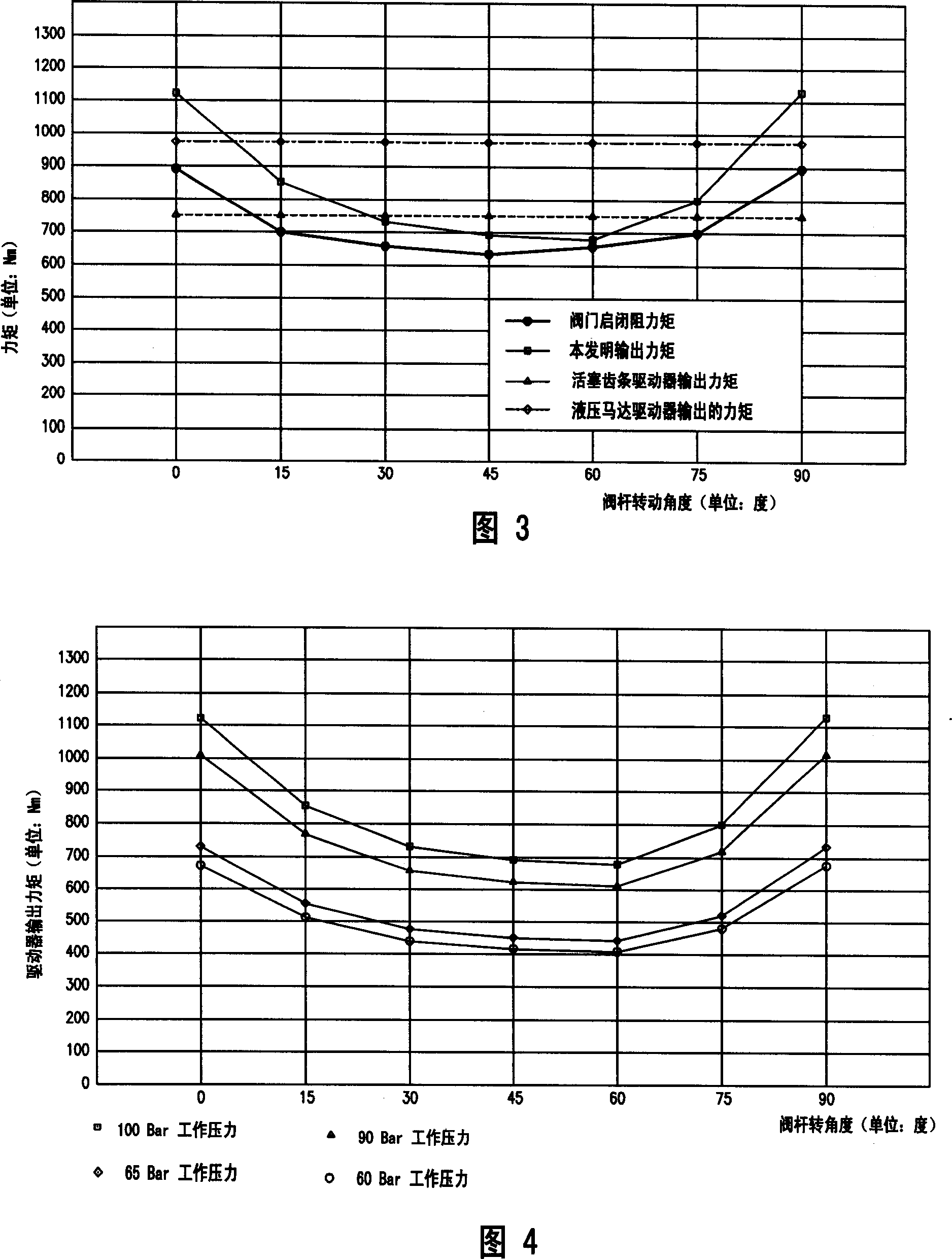
[0004] Whether it is a hydraulic motor drive device or a piston rack drive device, it has a constant valve opening and closing drive torque; however, during the actual opening and closing of the valve, especially when it is opened, due to the pipeline back pressure, Due to the inertia of the transmission medium and static friction, the required torque is not constant, but the torque is relatively large when opening and closing, and the torque is relatively small during the opening process.
In the prior art, in order to ensure sufficient torque to open and close the valve, a valve hydraulic drive device with a relatively large output torque has to be selected, which results in a large horse-drawn trolley, resulting in an increase in cost and a waste of resources

Method used


Image

  • Valve hydraulic driver
  • Valve hydraulic driver
  • Valve hydraulic driver

Examples


Embodiment Construction

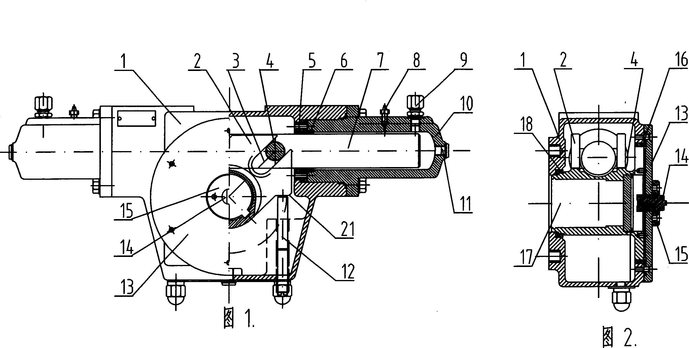
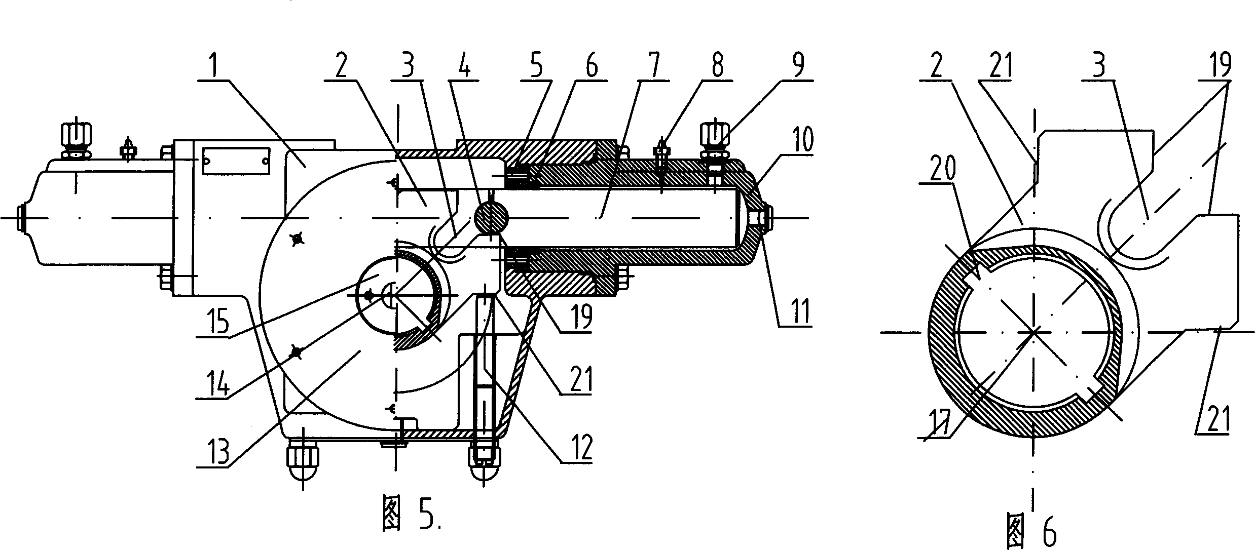
[0018] In the valve hydraulic actuator shown in FIG. 1 and FIG. 2 , the power source hydraulic cylinder includes a hydraulic cylinder barrel 10 and a piston rod 7 slidably placed in the hydraulic cylinder barrel 10 . Two hydraulic cylinder barrels 10 are symmetrically installed on the driver housing 1 , and the two opposite hydraulic cylinder barrels 10 are respectively sleeved on two ends of the piston rod 7 , and the piston rod 7 can slide left and right in the hydraulic cylinder barrel 10 . Each hydraulic cylinder 10 seals the piston rod 7 on the hydraulic cylinder 10 through the sealing ring 6 and the cylinder end cover 5 , so that the piston rod 7 is slidably supported on the driver housing 1 through the hydraulic cylinder 10 . Each hydraulic cylinder 10 is respectively equipped with an air release bolt 8 and a straight-through pipe joint 9, and the straight-through pipe joint 9 is directly connected with a pressure source or a manual pump in manual operation or in an emer...


PUM


Abstract

The invention discloses a valve hydraulic driver for controlling opening and closing of valve. The hydraulic driver comprises a driver shell, a piston rod and a hydraulic cylinder, wherein the piston rod is slidingly supported on the driver shell via the hydraulic cylinder; the a valve stem shifting yoke is rotatably supported on the driver shell, and a valve stem mounting hole and a shifting pin slot are arranged on the valve stem shifting yoke; and a valve stem shifting pin is fixedly arranged on the piston rod and slidingly positioned in the shifting pin slot on the valve stem shifting yoke. The valve stem shifting yoke is slidingly supported on the driver shell via an upper sliding sleeve and a lower sliding sleeve. The driver not only has large driving force and fast response speed, but also its output torque can be adapted with the variation rule of resisting torque for opening and closing valve. The invention has the advantages of reasonable structure and low cost; and can be widely used for controlling industrial pipeline valve in petroleum industry, chemical industry, ocean engineering and shipping industry.

Description

technical field [0001] The invention relates to a valve opening and closing device, in particular to a hydraulic drive device for controlling the valve opening and closing. Background technique [0002] A large number of valves are used in industrial pipelines in petroleum, chemical, marine engineering and shipbuilding industries. With the development of science and technology and the improvement of the degree of automatic control in the production process, the opening and closing control of valves, especially for the opening and closing control of valves that need to be operated remotely, mostly use electric, pneumatic or hydraulic to drive the opening and closing of valves. Hydraulic drive has been more widely used in the opening and closing control of valves because of its advantages of large driving force, strong fast dynamic response ability, excellent anti-interference performance, and convenient frequent and smooth reversing. [0003] At present, there are two main s...

Claims


Application Information

Patent Timeline
IPC IPC(8): F16K31/122
Inventor 刘庆中
Owner JIANGSU ZHONGAO CONTROL SYST TECH
Learn More