
Drilling well headframe plane rocking test set

A new device, a flat technology, applied in measuring devices, using optical devices to transmit sensing components, force/torque/work measuring instruments, etc., can solve the problems of complex mathematical calculations, and it is difficult to effectively reflect the overall swing of the derrick, etc. Achieve the effect of preventing construction accidents and derrick accidents

Inactive Publication Date: 2008-01-16
SOUTHWEST PETROLEUM UNIV
View PDF0 Cites 5 Cited by
  • Summary
  • Abstract
  • Description
  • Claims
  • Application Information

AI Technical Summary

Problems solved by technology

This requires the establishment of mechanical models, simulation analysis, time history response and other processes. Model establishment and mathematical calculations are very complicated, but it is difficult to effectively reflect the overall swing of the derrick

Method used


Image

  • Drilling well headframe plane rocking test set
  • Drilling well headframe plane rocking test set

Examples


Embodiment Construction

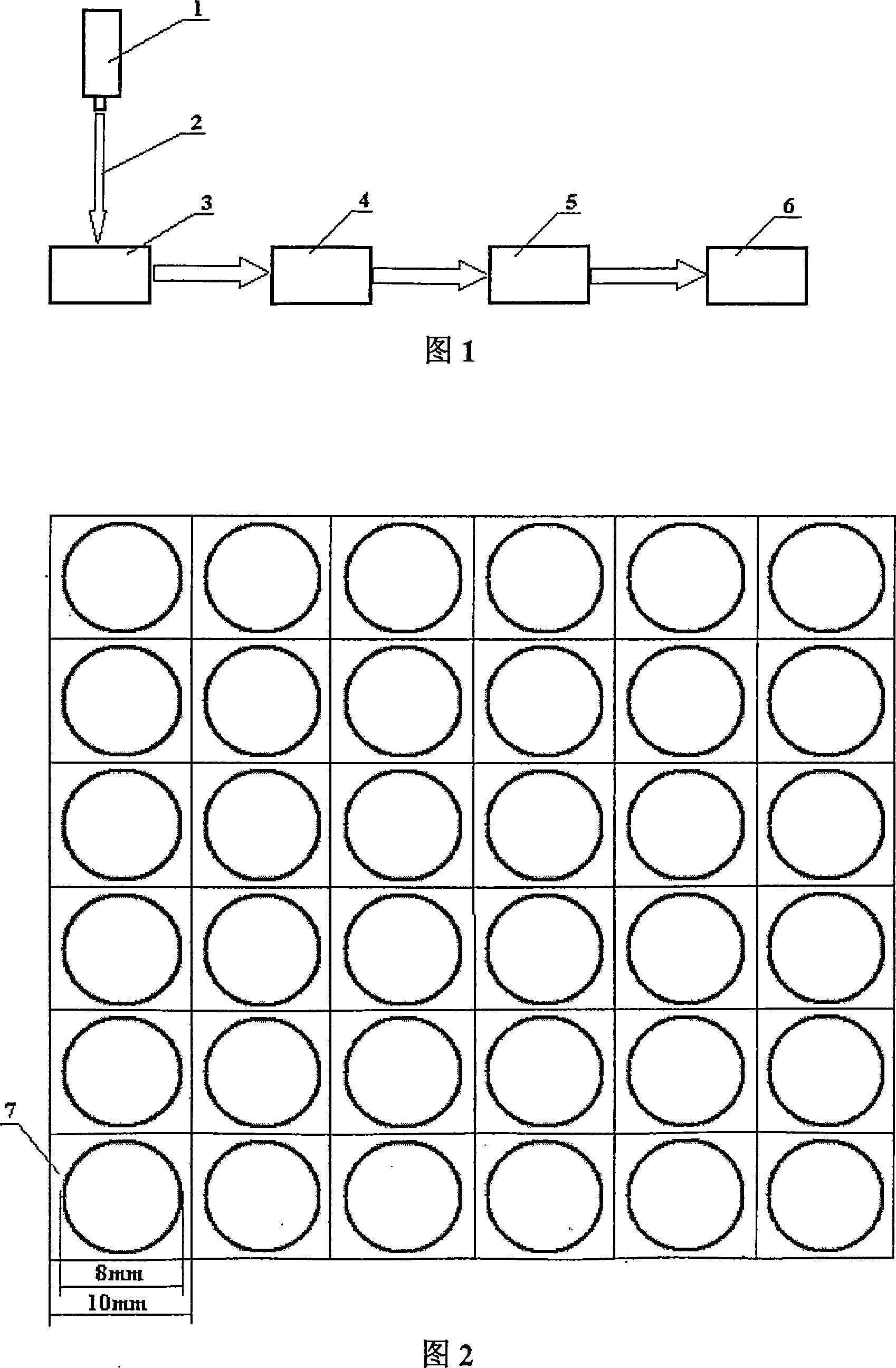
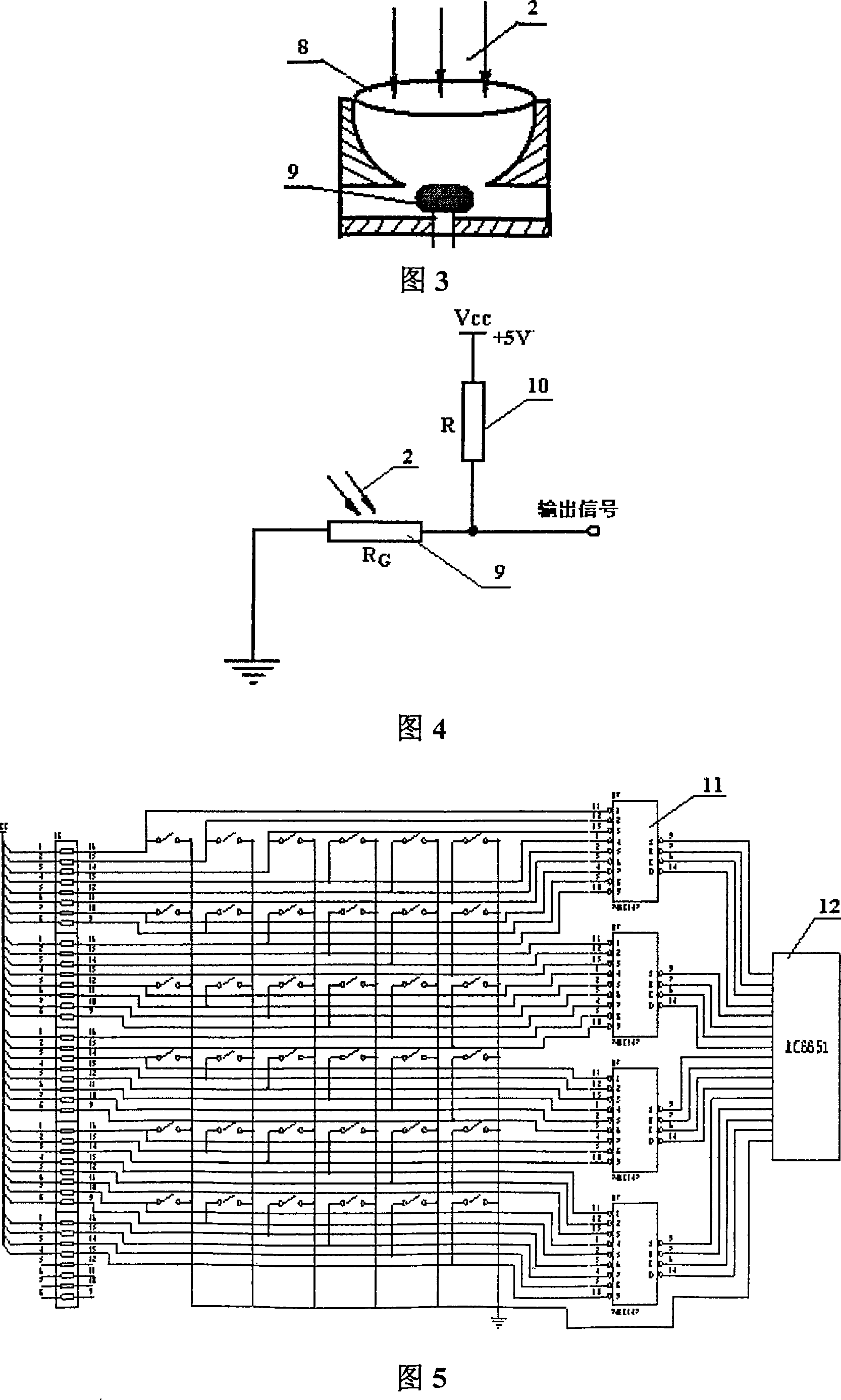
[0012] Install the laser 1 on the top of the drilling derrick. When the laser 1 swings with the sway of the derrick, the laser beam 2 is irradiated vertically downward to the plane photoelectric sensor array 3 placed horizontally on the ground, and the laser beam 2 is focused on the photoelectric sensor array through the concave mirror 8. on the photoresistor 9 in the When the photoresistor 9 is under normal light (no laser beam irradiation), its resistance value is about 3kΩ; when there is laser beam irradiation, its resistance value is about 0.3kΩ; About 3kΩ), under normal light, the output signal is about 2.5V, which can be regarded as high level. When there is laser beam irradiation, the output signal is about 0.5V, which can be regarded as low level, which meets the input level requirements of the data acquisition card. The output signal of the 36-channel photoelectric sensor array after photoelectric signal conversion is sent to four 10-4-wire encoders 11 for encoding. A...


PUM

PropertyMeasurementUnit
diameteraaaaaaaaaa
poweraaaaaaaaaa
electrical resistanceaaaaaaaaaa

Abstract

The invention relates to a new device capable of intuitively and effectively monitoring planar swinging motion of drill derrick. The device comprises a laser, a planar photoelectric sensor array, an encoder, a computer interface card, and a software program. The laser is disposed at the top of the drill derrick, when the laser swings with the motion of the drill derrick, the laser beam perpendicularly and downwardly irritates on the photoelectric sensor array that is horizontally installed on the ground, the photoelectric sensor in the array senses laser and outputs voltage signal with certain amplitude, the voltage signal after coding is inputted into a computer via an acquisition card for processing, displaying, storing and alarming when beyond limit. The invention can intuitively and effectively record the macroscopic swinging motion of the drill derrick, so as to provide practical information for stress analysis and fault evaluation of the drill derrick and effectively prevent occurrence of accidents on the drill derrick. The device can also be used for monitoring swinging motion of bridges and high-rise buildings under running process and natural draught, so as to effectively prevent the occurrence of construction accidents.

Description

technical field [0001] The invention relates to a new device which can directly and effectively test the plane swing of the drilling derrick, which can be applied to the drilling derrick to provide practical information for the stress analysis and fault evaluation of the drilling derrick, and can effectively prevent the occurrence of derrick accidents. Background technique [0002] During the drilling process, the drilling derrick has a heavy load and is excited by various vibration sources, so various severe vibrations will inevitably occur. Due to factors such as derrick installation asymmetry, work load asymmetry, wind influence (especially offshore platform drilling derrick) and other factors, the derrick will produce plane swing, generally up to 30cm×30cm. This plane swing of the drilling derrick is the most dangerous safety hazard during the operation of the derrick. [0003] At present, the swing test of the derrick mainly analyzes its structural dynamic characterist...

Claims


Application Information

Patent Timeline
Patent Type & Authority Applications(China)
IPC IPC(8): G01D5/26G01L5/00
Inventor 何道清
Owner SOUTHWEST PETROLEUM UNIV
Learn More