Motor with brush

A technology of motors and brushes, applied in the direction of brush manufacturing, current collectors, casings/covers/supports, etc., can solve problems such as inability to cope, and achieve the effects of prolonging life, suppressing wear, and improving vibration attenuation characteristics

Inactive Publication Date: 2008-01-16
SANKYO SEIKI MFG CO LTD
View PDF1 Cites 8 Cited by
  • Summary
  • Abstract
  • Description
  • Claims
  • Application Information

AI Technical Summary

Problems solved by technology

However, there is a problem that it is not possible to meet this requirement if only a buffer member is arranged at the base of the brush and its vicinity as in the structure disclosed in Patent Document 1.

Method used


Image

  • Motor with brush
  • Motor with brush
  • Motor with brush

Examples


Embodiment Construction

[0038] Embodiments of the present invention will be described below with reference to the drawings.

[0039] (The overall structure of the brushed motor)

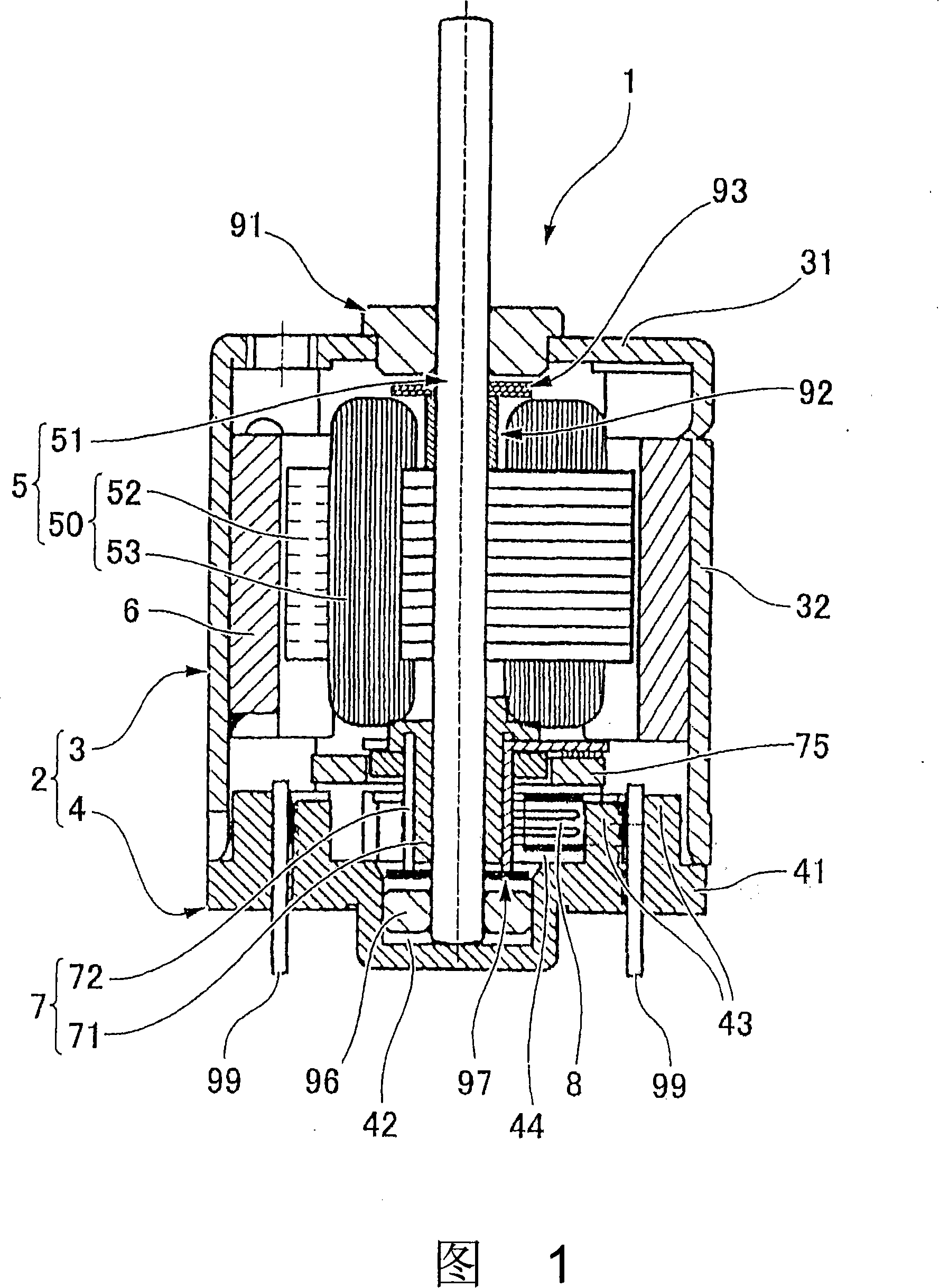
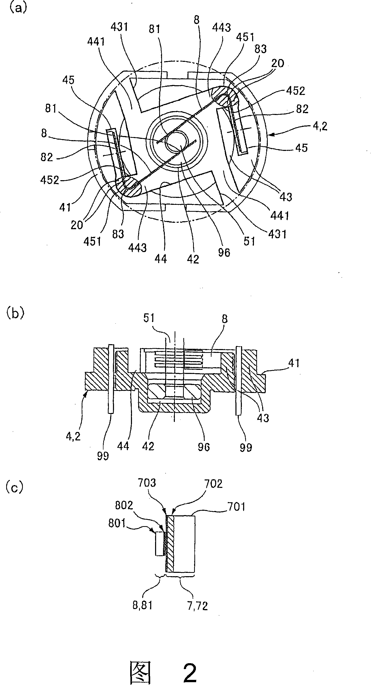
[0040] FIG. 1 is a cross-sectional view showing the overall structure of a brushed motor to which the present invention is applied. Fig. 2(a) is a top view showing the brush and the brush holder pulled out from the brushed motor shown in Fig. 1, Fig. 2(b) is a cross-sectional view thereof, and Fig. 2(c) is a view of the brush and the commutator Explanatory diagram of the sliding part.

[0041] In FIG. 1 , the brushed motor 1 of this embodiment is a small DC motor with a brush, and the output end side of the rotating shaft 51 protrudes from the upper end surface 31 of the cup-shaped motor case 3 . Inside the motor housing 3 , an iron core 52 made of laminated magnetic plates is fixed to an approximately central portion in the axial direction of the rotating shaft 51 by press-fitting or the like. A plurality of salient pol...


PUM


Abstract

A motor with a brush having a rotor, a commutator, a brush and a stationary side member is provided. The commuator is rotatable with the rotator and the stationary side member retains a base end side of the brush in such a manner that a top end side of the brush elastically contacts an outer circumference surface of the commutator, and retains a permanent magnet in such a manner that the permanent magnet faces the rotor. The brush is equipped with a bent part on a way from the base end side toward the top end side, as well as a damper member fixed to both the bent part of the brush and the stationary side member.

Description

technical field [0001] The present invention relates to a brushed motor which uses a commutator and a brush for commutation. Background technique [0002] In a brushed motor, commutation is performed by elastically bringing metal brushes into contact with an outer peripheral surface of a commutator that can rotate integrally with a rotor. The brush has its base end side fixed to the brush holder, and is bent at a position midway from the base end side toward the front end side so that the front end side contacts the outer peripheral surface of the commutator. In such a brushed motor, when the tip side of the brush vibrates violently due to the rotation of the rotor (rotation of the commutator), mechanical noise is generated. Therefore, a technique has been proposed in which a cushioning member is formed by applying an adhesive material composed of a water-soluble acrylic latex whose initial viscosity is adjusted by polymerizing styrene monomer on the outer side of the brush...

Claims


Application Information

Patent Timeline
Patent Type & Authority Applications(China)
IPC IPC(8): H01R39/24H01R43/12H02K13/00
CPCH02K5/24H02K5/145H01R39/24H01R39/39
Inventor 赤羽诚
Owner SANKYO SEIKI MFG CO LTD
Why Eureka
Try Eureka