A method for common transfer of multiple pairs and transmission terminal and receiving terminal

It is a technology of receiving end and sending end, which is applied in the direction of line transmission parts, transmission system, digital transmission system, etc. It can solve the problems of not being able to carry bits, dissatisfaction, waste of channel resources, etc., to achieve performance improvement, lengthen signal transmission distance, The effect of increasing the transmission rate

Inactive Publication Date: 2008-01-16
HUAWEI TECH CO LTD
View PDF0 Cites 18 Cited by
  • Summary
  • Abstract
  • Description
  • Claims
  • Application Information

AI Technical Summary

Problems solved by technology

Although the signal-to-noise ratio between 203 and 204 is greater than zero, it cannot be used to carry data, which is a great waste. Therefore, MIMO technology does not give full play to the advantages of multi-pair joint processing.
[0023] In addition, depending on the actual application environment, the noise of each pair of lines and the attenuation of the channel are also different. As shown in Figure 7, only the s

Method used


Image

  • A method for common transfer of multiple pairs and transmission terminal and receiving terminal
  • A method for common transfer of multiple pairs and transmission terminal and receiving terminal
  • A method for common transfer of multiple pairs and transmission terminal and receiving terminal

Examples


Example Embodiment

[0074] Example one:

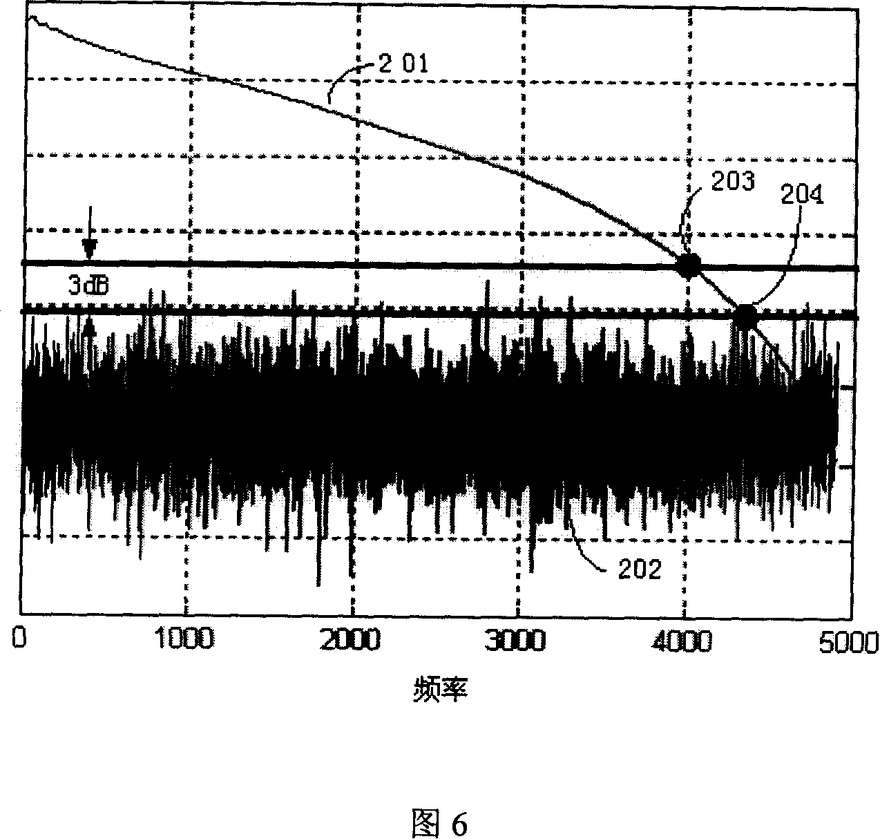
[0075] According to the signal-to-noise ratio of each pair of lines, the frequency band corresponding to the signal-to-noise ratio greater than or equal to 3dB is regarded as the frequency band satisfying the load-bearing conditions, and the frequency band corresponding to the signal-to-noise ratio less than 3dB is regarded as the frequency band not meeting the load-bearing conditions. The transmission information is divided into N+M (M is greater than or equal to 1) parts. Among them, the N parts of the transmission information are carried by the frequency bands that meet the carrying conditions of the N pairs of lines, that is, the N parts of the transmission information are respectively carried by the N pairs of lines. Transmission, using the existing MIMO working mode, and the remaining M partial transmission information uses at least two frequency segments that do not meet the bearing conditions to be repeatedly carried, that is, any partial information ...

Example Embodiment

[0087] Embodiment two:

[0088] The schematic diagram of the principle of the sending end and the receiving end of this embodiment is shown in FIG. 13.

[0089] The transmitting end includes a modulator group composed of four modulators, a transmitter group composed of four transmitters, an encoder group composed of ten encoders, and a selection combiner group, where the selection combiner The group includes a selector and a combiner group composed of four combiners; the ten output terminals of the encoder group are respectively connected to the ten input terminals of the selector, and the four output terminals of the selector are respectively connected to the four combiners. The input ends are connected, the output ends of the four combiners are respectively connected to the input ends of the four modulators, and the output ends of the four modulators are respectively connected to the input ends of the four transmitters.

[0090]First, the encoder group encodes the transmission i...


PUM


Abstract

The invention discloses a multi-paired line co-transportation method and a delivering end and a receiving end. A multi-paired line co-transportation method, wherein N pairs are set as N greater than or equal to 2, includes that the delivering end divides the data to be delivered into N+M parts to encode respectively, then N+M encoded signals are obtain to be modulated respectively, and the modulated signals are delivered to the receiving end via N-paired lines, wherein M is larger than or equal to 1; the receiving end demodulates and decodes the received signals to recover the delivered data. The delivering end comprises a modulator set and a deliver set, and also comprises a encoder set and a selecting combiner set. The receiving end comprises a modem set and a receiver set, and also comprises a decoder set and a deselecting combiner set. The invention increases the combined transportation capacity of multi-paired lines.

Description

[technical field] [0001] The invention relates to the field of communication technology, in particular to a method for common transmission of multiple pairs of wires, a sending end and a receiving end. [Background technique] [0002] Digital Subscriber Line (Digital Subscriber Line, DSL) technology is a high-speed transmission technology for data transmission through telephone twisted pair, ie, Unshielded Twist Pair (Unshielded Twist Pair, UTP). DSL includes Asymmetrical Digital Subscriber Line (ADSL), Very-high-bit-rate Digital Subscriber Line (VDSL), and users based on Integrated Services Digital Network (ISDN) Digital Subscriber Line (ISDN Digital Subscriber Line, IDSL) and Single-pair High-bit-rate Digital Subscriber Line (Single-pair High-bit-rate Digital Subscriber Line, SHDSL), etc. [0003] Among various digital subscriber line technologies (xDSL), in addition to DSL with baseband transmission such as IDSL and SHDSL, DSL with passband transmission uses frequency div...

Claims


Application Information

Patent Timeline
IPC IPC(8): H04J15/00H04L27/00H04J99/00
CPCH04L5/0044H04Q2213/1329H04Q2213/13399H04Q2213/13389H04L5/20H04B3/32H04L5/0023H04L2012/5618H04L12/5601H04L2012/5665H04L12/2881H04L12/4633H04Q2213/13204H04Q11/0428H04L5/006H04M11/062H04Q2213/13196
Inventor 石清泉
Owner HUAWEI TECH CO LTD
Why Eureka
Try Eureka