Manufacturing method of optical film

A manufacturing method and technology of optical thin films, applied in chemical instruments and methods, optics, nonlinear optics, etc., can solve problems such as changes in orientation characteristics and inability to obtain a uniform orientation state

Inactive Publication Date: 2008-01-16
NITTO DENKO CORP
View PDF2 Cites 7 Cited by
  • Summary
  • Abstract
  • Description
  • Claims
  • Application Information

AI Technical Summary

Problems solved by technology

[0008] In the above-mentioned substrate, since the surface state of the part where the block occurs changes, there is a problem that even if the substrate is subjected to a rubbing treatment, the alignment characteristics of the part where the block occurs and other parts change, and the liquid crystal molecules form domains. Therefore, a uniform orientation state cannot be obtained

Method used


Image

  • Manufacturing method of optical film
  • Manufacturing method of optical film
  • Manufacturing method of optical film

Examples


Embodiment 1-1

[0071] (1) Friction treatment

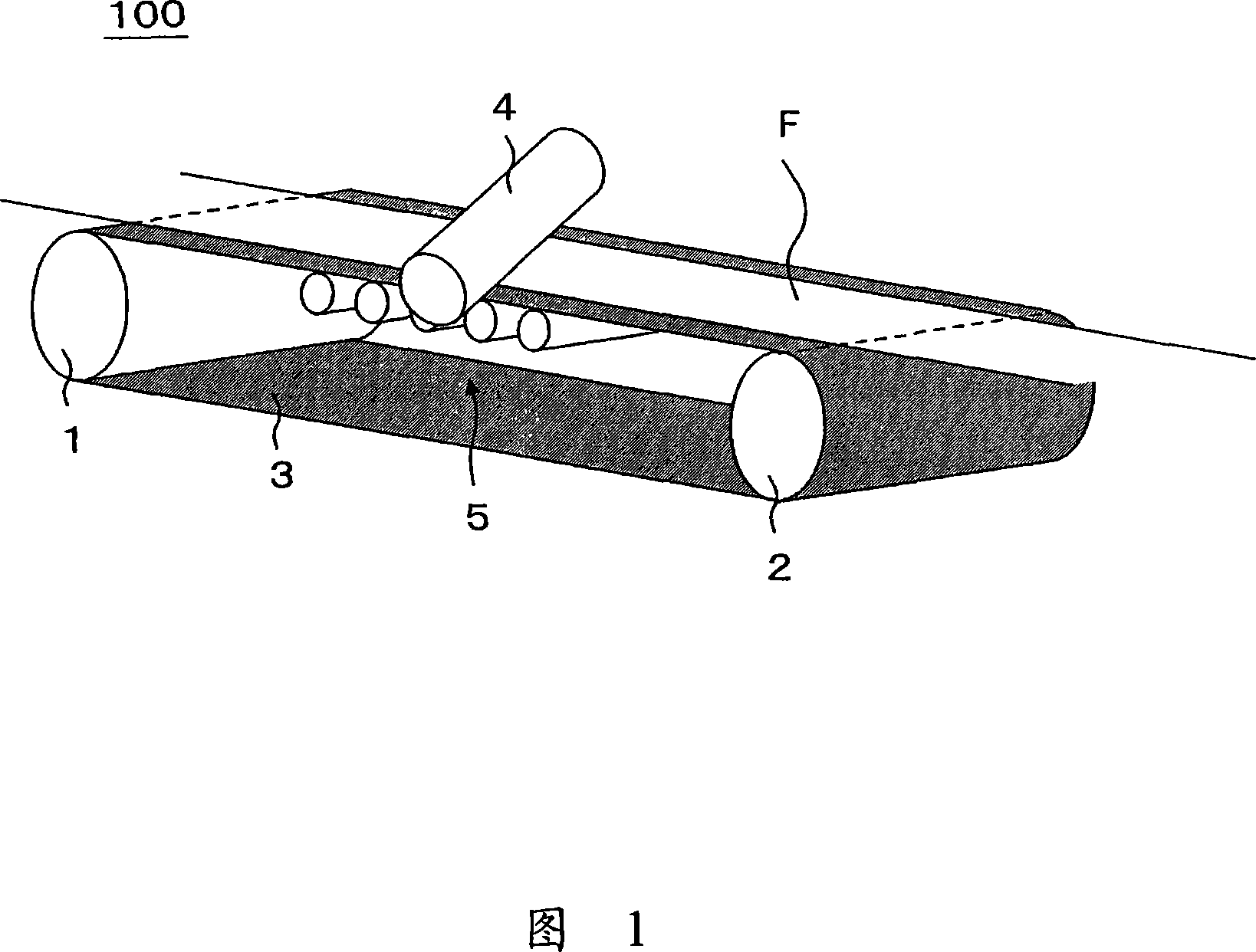
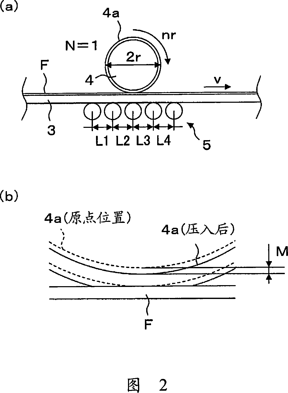
[0072] The rubbing treatment device 100 shown in FIGS. 1 and 2 was used to perform rubbing treatment on a saponified triacetyl cellulose film having a thickness of 40 μm. In addition, the mirror finish of the surface of the conveyor belt 3 is Ra=0.01μm, the outer diameter of the driving rollers 1 and 2 is 550mm, the transport speed of the film is 5m / min, the outer diameter of the support roller 5 is 50mm, and each adjacent support The distances L1 to L4 between the rollers 5 are all 80 mm. In addition, the radius of the friction roller 4 (including the raised cloth 4a) was 76.89 mm, and a friction roller wound with a raised cloth made of rayon was used. The rotation axis of the rubbing roller 4 is inclined by 24.3° with respect to the transport direction of the film, the rotation speed is 1500 rpm, and the pressing amount is 0.3 mm. The friction strength under these conditions is 2609 mm.

[0073] (2) Preparation of coating liquid containing liquid ...

Embodiment 1-2

[0079] A retardation film was manufactured based on Example 1, except that the amount of press-fitting of the rubbing roller 4 was set to 0.4 mm (the friction strength at this time was 3479 mm).

Embodiment 1-3

[0081] A retardation film was manufactured based on Example 1, except that the amount of pressing of the rubbing roller 4 was set to 0.5 mm (the friction strength at this time was 4349 mm).


PUM

PropertyMeasurementUnit
thicknessaaaaaaaaaa
surface roughnessaaaaaaaaaa
radiusaaaaaaaaaa

Abstract

This invention provides a process for producing an optical film, comprising a rubbing treatment step of rubbing a surface of a continuous plastic film (F) by a rubbing roll (4) around which a brushed cloth (4a) has been wound, a coating step of coating liquid crystalline molecules on the surface of the film, and a fixation step of fixing the liquid crystalline molecules. The process is characterized in that, in the rubbing treatment step, the film is supported on and transported by a transfer belt (3) having a metal surface, a plurality of backup rolls (5) are provided so as to support the lower surface of the transfer belt for supporting the film and to face the rubbing roll, and the rubbing strength RS defined by the following equation (1) is set to not less than 2600 mm (more preferably not less than 3400 mm). RS = NM (1 + 2prr / v) (1).

Description

Technical field [0001] The present invention relates to a method of manufacturing an optical film used for optical compensation, anti-reflection, etc. of a liquid crystal display device, and more particularly to a method of manufacturing an optical film having uniform optical properties at low cost. Background technique [0002] Conventionally, various optical elements manufactured by coating and aligning a liquid crystal material on the surface of a substrate are known. In the manufacturing process of such an optical element, in order to orient the liquid crystal material on the surface of the substrate, a rubbing treatment is generally performed to wipe the surface of the substrate with a raised cloth in one direction. For example, when the optical element is a liquid crystal cell, rubbing treatment is performed with a glass substrate unit as a base material. However, in the case of an optical element (optical film) using a plastic film as a base material, compared to the rubbi...

Claims


Application Information

Patent Timeline
Patent Type & Authority Applications(China)
IPC IPC(8): G02B5/30C08J7/04B05D3/12G02F1/13363B32B7/02
CPCC09K19/2007C08J7/18G02F1/133784C08J2301/12G02F1/133305C09K2019/0448G02F1/13G02F1/1337
Inventor 秦和也川本育郎米泽秀行上条卓史梅本清司
Owner NITTO DENKO CORP
Why Eureka
Try Eureka