Connection system between capacitor batteries

A technology for connecting systems and capacitors, applied in the direction of capacitors, capacitor terminals, battery pack components, etc., can solve the problems of not easy to disassemble, easily damaged components, not fast enough, etc., to achieve rapid connection and disassembly, small inductance, and low cost. Effect

Inactive Publication Date: 2008-01-16
SEMIKRON FUER GLEICHRICHTERBAU & ELEKTRONIK
View PDF0 Cites 11 Cited by
  • Summary
  • Abstract
  • Description
  • Claims
  • Application Information

AI Technical Summary

Problems solved by technology

[0007] The connection arrangement of the prior art, using the plate rolling process, creates more problems, that is to say, to reconnect two conductive plates of different polarity separated by an insulating layer, between the connecting pieces is currently Connected by bolts / nuts, as a result, not easy to disassemble, which means that the bolts need to be completely unscrewed, which is not quick enough and can easily damage the components

Method used


Image

  • Connection system between capacitor batteries
  • Connection system between capacitor batteries
  • Connection system between capacitor batteries

Examples


Embodiment Construction

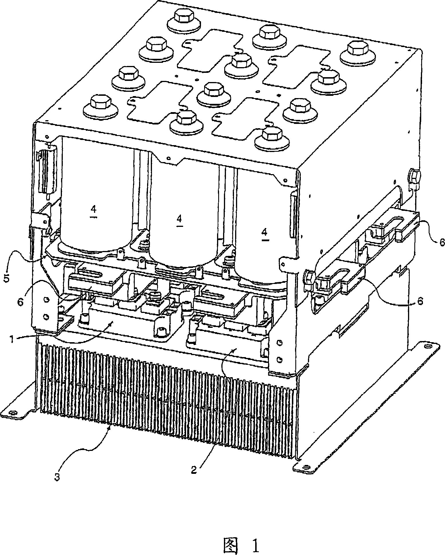
[0042] Referring to Figure 1, IGBT module 1 and module 2 form an inverter together with other components. The middle layer is between the radiator 3 and the upper capacitor box. The radiator helps to dissipate heat. The capacitor 4 is welded or assembled on the bus bar. On the 5 plane, the bus bar 5 is composed of two thin conductive plates. The conductive plates are connected to two capacitors with different polarities and separated by an insulating layer.

[0043] A protrusion 6 is provided around the bipolar plate, and the protrusion 6 extends beyond the block, so that the inverter component is connected with other same components.

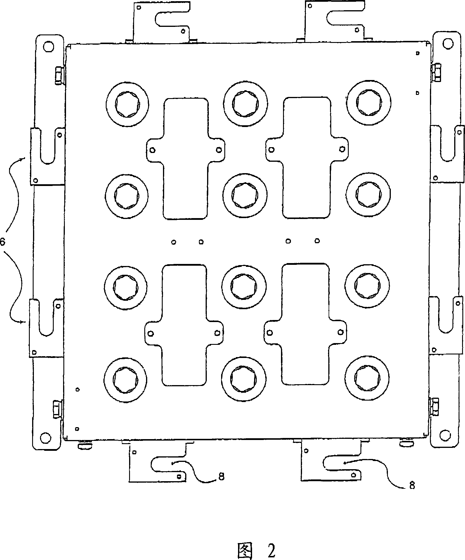
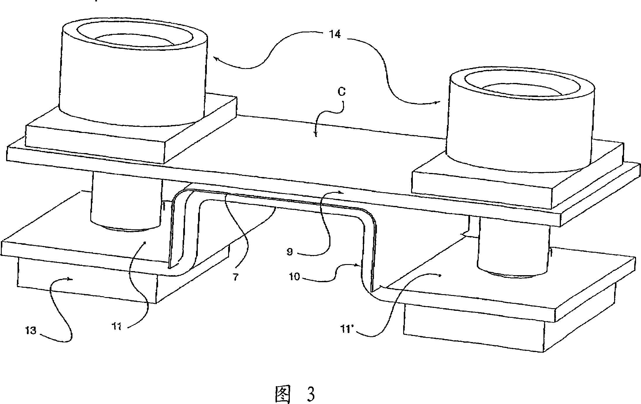
[0044] Figure 2 more clearly shows the shape of the protrusions 6 protruding around. The protrusions 6 have lateral sliding grooves 8 which can position the connecting system between the components (see Figure 3), especially with The fastening devices of the system are matched.

[0045] In the installation embodiment of the inverter assembly shown ...


PUM


Abstract

The invention concerns a connection system between batteries or banks of capacitors (4) associated with a circuit, for example of the inverter type and whereof the capacitors (4) are connected by a busbar (5) consisting of two thin bars of different polarities stacked and separated by an insulating layer. Each busbar (5) comprises at least one protuberance (6, 6') designed to co-operate with a linking member (C, C') between two protuberances (6, 6') derived from two batteries or banks of adjacent capacitors (4). The linking member comprises two conductive strips (9, 10; 9', 10') designed to be contacted each with the bars of same polarity of two opposite protuberances (6, 6'), said strips (9, 10; 9', 10') being arranged on either side of an insulating layer (7, 7'). One of the protuberances (6, 6') or of each co-operating zone of the linking member (C, C') with one protuberance (6, 6') comprises a clamp forming a slide enabling the other to be slidingly positioned perpendicular to the axis of the link. Clamping/releasing means (12, 13, 14) enable the linking member (C, C') to be fixed to each protuberance (6, 6'), said means being maintained as one single assembly upon release.

Description

Technical field [0001] The present invention relates to a connection system between batteries or bancs having a circuit such as capacitors of inverter components. These batteries are composed of a plurality of capacitors, and the capacitors are connected by a bus bar. The bus bar in the prior art is formed by two plates or thin conductive plates with different polarities, stacked together and separated by an insulating layer. These batteries are obviously integrated with the blocs of the components, and the blocks are relatively large, especially the blocks used to install the inverter as described above. Background technique [0002] The connection between multiple capacitor batteries (batteries de condensateurs) will in fact be realized through additional circuit parts such as a circuit, which may result in an overall electrical induction arrangement, especially on the connection surface. The connection between the blocks of these batteries creates a possibility of partial repl...

Claims


Application Information

Patent Timeline
Patent Type & Authority Applications(China)
IPC IPC(8): H01G2/04H01G9/008H01M50/507
CPCY02E60/12H01M2/202H01G2/04H01G4/38Y02E60/10H01M50/507
Inventor 布里亚格·阿兰菲利普·莱布里顿让·F·萨戈斯
Owner SEMIKRON FUER GLEICHRICHTERBAU & ELEKTRONIK
Why Eureka
Try Eureka