Light source with replaceable lamp wick

A technology for light source devices and wicks, which can be applied to projection devices, optics, instruments, etc., and can solve the problems of high cost, high production cost of reflectors, and poor cooling performance.

Inactive Publication Date: 2008-01-23
KTO TECH
View PDF1 Cites 4 Cited by
  • Summary
  • Abstract
  • Description
  • Claims
  • Application Information

AI Technical Summary

Problems solved by technology

[0005] But this system has the following disadvantages: (1) when replacing the light source, the positioning problem of its wick and the lampshade, and the difficulty that the wick must be adjusted and placed on the positioning point; (2) the replacement of the light source is too complicated and must It is inconvenient to disassemble the two mirrors, replace the wick, and then adjust the positions of the two mirrors; (3) This assembly method also reduces the effective area of ​​the reflective mirror surface, that is, the area of ​​the reflective coating is reduced to meet the assembly needs. This will prevent part of the light from being collected; (4) dismantling the system in order to replace the light source will easily pollute the light-collecting mirror and wick tube. If dust, oil stains, etc. are attached to it, the light projection efficiency of the entire system will decrease (5) Due to the poor heat dissipation of the wick, the service life of the wick is shortened; (6) Since there are more than one reflector assembly, the manufacturing cost is higher than that of one reflector lampshade; (7) It is composed of two reflectors The lampshade volume is larger than the lampshade of a reflector
But this type of system has some new disadvantages: (1) the wick of this system is completely covered in the two reflectors. Once the life of the wick is exhausted, the system has to be disassembled to replace the light source, and disassembly is easy. The mirror surface and the new wick tube are polluted, and the light is easily scattered and lost; (2) At least one mirror must be disassembled, but it is very inconvenient, and it is more difficult to assemble and calibrate when restoring the system; (3) The assembly method causes other The effective area of ​​the reflecting mirror is reduced, that is, the area of ​​the reflecting coating is reduced to meet the needs of assembly; (4) the production cost of the two-sided reflecting mirror is still high; (5) it is not conducive to the heat dissipation of the system operation, and the risk of explosion of the lamp is increased. The relationship between poor cooling cannot replace the light source in real time; (6) Overheated system reduces the life of the light bulb

Method used


Image

  • Light source with replaceable lamp wick
  • Light source with replaceable lamp wick
  • Light source with replaceable lamp wick

Examples


Embodiment Construction

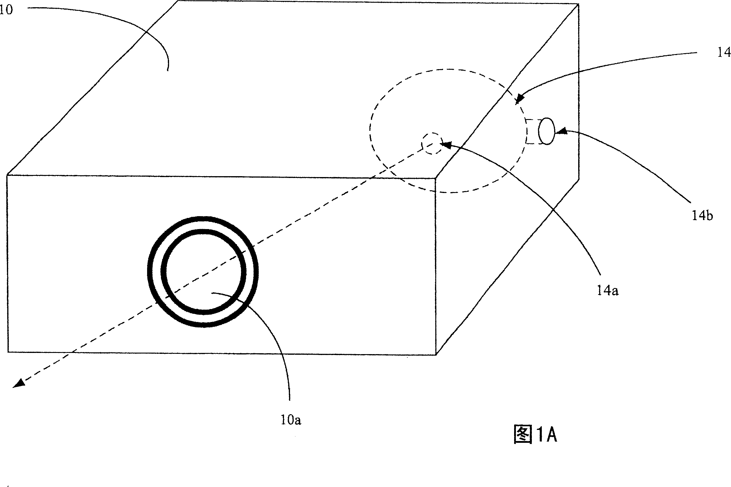
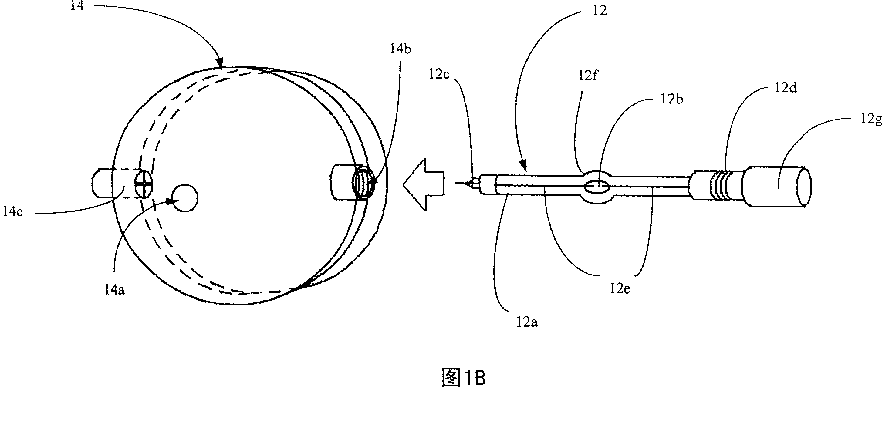
[0027] Please refer to FIGS. 1A-1B . FIGS. 1A-1B are schematic diagrams of a projector based on a light source device with a replaceable wick according to the present invention. As shown in FIG. 1A , the projector 10 of the present invention is mainly composed of a light source 12 (as shown in FIG. 1B ), a lampshade 14 , and a projection lens 10 a of the light source device with replaceable wicks of the present invention. The lampshade 14 is installed inside the projector 10 , and all the positioning port electrode holders 14 b can be observed from the appearance of the projector 10 .

[0028] As shown in FIG. 1B , the light source 12 is mainly composed of a wick tube 12 a , a wick 12 b , and electrode pairs 12 e extending from the wick 12 b in two directions. The electrode pair 12e is electrically connected to the electrode cap 12d and the cross electrode 12c at both ends of the wick tube 12a, and the handle portion 12g is extended from the electrode cap 12d. The wick tube 1...


PUM


Abstract

The utility model discloses an illuminant apparatus of which the lamp wick is removable. The plug-in type replacement can be adopted for the change of the lamp wick tube, so shat the problem concerning the calibration and location of the two reflectors for both the lamp wick and the lamp screen can not be considered. The illuminant is equipped with the grip. So, the system will not be contaminated as conducting the replacement with the hands. The smooth axis of the illuminant forms the vertical position with the lamp tube, so as to avoid the dark field in the middle position. Meanwhile, the lamp can be free from the non-uniformity of heating. Thus, illuminant blinking arising from the poor thermal balance can be avoided. The end of the lamp wick tube is covered by the sheet copper, so as to improve the electrifying and the heat rejection. The two reflector surfaces are fixed at a relative position so as to improve the problem concerning the location of two reflector surfaces as replacing the lamp wick. Also, the manufacturing cost is lowered.

Description

technical field [0001] The invention relates to a light source device with a replaceable wick, in particular to a light source device with a replaceable wick which is easy to locate, easy to assemble and reduces pollution in the system. Background technique [0002] The display principle of a projection display is basically the same as that of all projectors. The projector first irradiates light to the image display component to generate an image, which is then projected through the lens. The image display unit of the projector includes a transmission type that uses transmitted light to generate an image and a reflective type that uses reflected light to generate an image. No matter which type, the light of the projection lamp is divided into three colors of red, green and blue, and then images of various colors are produced. Because the component itself can only display monochrome, it is necessary to use 3 components to generate 3 color components respectively. Then the ...

Claims


Application Information

Patent Timeline
IPC IPC(8): G03B21/14
Inventor 欧阳盟黄诗玮李信宏
Owner KTO TECH
Why Eureka
Try Eureka