Magnetic suspension device used for measuring spherical spinner pole axis deflection angle and measurement method thereof

A technology of polar axis declination and spherical rotor, which is applied in the direction of measuring device, using electric/magnetic device to transmit sensing components, using electric device, etc., can solve the problems of high difficulty, high technical difficulty and high installation accuracy

Inactive Publication Date: 2008-01-30
INST OF ELECTRICAL ENG CHINESE ACAD OF SCI
View PDF0 Cites 33 Cited by
  • Summary
  • Abstract
  • Description
  • Claims
  • Application Information

AI Technical Summary

Problems solved by technology

These methods all need to engrave diffuse reflection patterns on the surface of the rotor, that is, the spherical surface, which is technically difficult, and the reflection effect of the spherical surface on light is also poor.
The second method requires the engraved line to be symmetrical to the equator, which is more difficult, and requires the use of four optical fiber sensors placed orthogonally to each other, which requires high installation accuracy and high cost
[0004] However, electrost

Method used


Image

  • Magnetic suspension device used for measuring spherical spinner pole axis deflection angle and measurement method thereof
  • Magnetic suspension device used for measuring spherical spinner pole axis deflection angle and measurement method thereof
  • Magnetic suspension device used for measuring spherical spinner pole axis deflection angle and measurement method thereof

Examples


Embodiment Construction

[0017] The present invention will be further described below in conjunction with the accompanying drawings and specific embodiments.

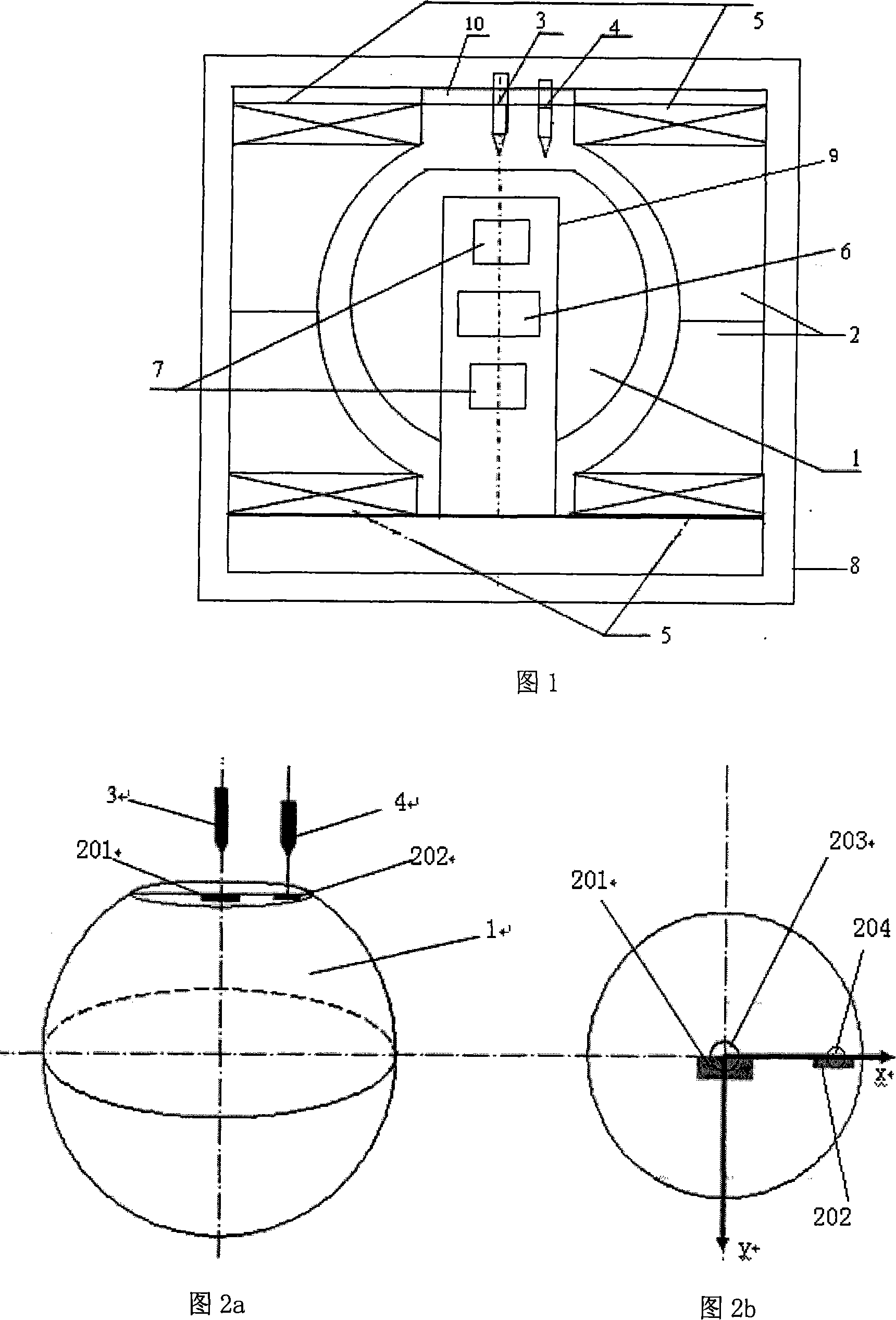
[0018] As shown in Figure 1, the low-temperature superconducting magnetic levitation device of the present invention includes: superconducting niobium ball rotor 1, niobium tile 2, polar axis optical fiber sensor 3, rotational speed optical fiber sensor 4, superconducting coil 5, superconducting motor 6, torque device 7 , low temperature Dewar 8, center column 9, copper plate 10. The cryogenic Dewar 8 located on the outermost layer of the device is cooled by cryogenic liquid helium, providing a 4.2K cryogenic environment for the entire system. The upper and lower niobium tiles 2 with spherical inner surfaces are arranged opposite to each other to form a spherical cavity. The hollow superconducting niobium ball rotor 1 is located in the spherical cavity and sleeved on the central column 9 . A superconducting motor 6 and two torque devices 7 ar...


PUM


Abstract

A magnetic levitation device and measurement method used for measuring the angle of spherical rotor polar axes, including low-temperature Dewar (8), superconducting suspension coil (5), superconducting niobium-rotor (1), niobium watts (2), superconducting motor (6), torque (7), centre column (9), copper (10), polar axes optical fiber sensor (3) and rev speed optical fiber sensor (4). The Superconducting niobium-rotor (1) is arranged in the spherical cavity formed by the upper and the lower relative niobium watts whose inner surfaces are spherical, and sleeves on the center column (9); two circular superconducting coils (5) are sleeved on the upper and the lower Niobium watts (2). The top of the rotor is produced into plane with diffuse reflection graphic. Two optical axis of the optical fiber sensor are perpendicular to the top plane of rotor and fix in the copper (10). The measurement method of the invention is used for measuring the angle of spherical rotor polar axes, adopts the non-contact type reflection intensity modulated optical fiber sensor to measure the displacement offset signal of the rotor polar axes, and uses the sophisticated two-phase lock-in amplifier to process signal, which has high precision.

Description

technical field [0001] The invention relates to a magnetic levitation device for measuring the polar axis deflection angle of a rotor and a method for measuring the pole axis deflection angle of the rotor, in particular to a low temperature superconducting spherical rotor magnetic levitation device and a method for measuring the polar axis deflection angle of the spherical rotor. Background technique [0002] Under the action of the suspension force, the spherical rotor rotates around the polar axis at high speed and has a certain angular momentum, trying to keep the orientation of its rotation axis relative to the inertial space unchanged. This characteristic is widely used in positioning and orientation systems. At present, photoelectric reading schemes are used to measure the polar axis deflection angle of spherical rotors. One is the polar axis-equator D-shaped engraving scheme, that is, the intersection point between the rotor surface and the polar axis, that is, the pol...

Claims


Application Information

Patent Timeline
IPC IPC(8): G01B11/26G01B7/30G01D5/353G01D5/14
Inventor 崔春艳胡新宁王秋良赵尚武
Owner INST OF ELECTRICAL ENG CHINESE ACAD OF SCI
Why Eureka
Try Eureka