Plane fluorescent lamp

A fluorescent lamp and flat technology, applied in the field of fluorescent lamps and flat fluorescent lamps, can solve the problems of limiting the size of the discharge gap, difficult to improve the luminous efficiency, and reducing the brightness of the backlight source, so as to increase the discharge gap, improve the brightness and luminous efficiency, and achieve uniform brightness. Sex-enhancing effect

Inactive Publication Date: 2010-05-19
XI AN JIAOTONG UNIV
View PDF5 Cites 0 Cited by
  • Summary
  • Abstract
  • Description
  • Claims
  • Application Information

AI Technical Summary

Problems solved by technology

[0005] (1) In order to prevent mutual interference between adjacent discharge luminescent rows, there is a wide non-luminous area between adjacent luminescent rows. At the same time, in order to avoid micro-discharge instability, adjacent protrusions on the cathode cannot be too close. Therefore, there is also a large non-luminous area between two adjacent micro-discharge areas, so that the brightness uniformity of the fluorescent lamp can only reach 80%. to make the brightness uniformity more than 90%, but this will reduce the brightness of the backlight
[0006] (2) The area of ​​the non-luminous area between two adjacent micro-discharge areas will increase with the increase of the discharge gap. Under the condition of ensuring stable and uniform discharge, the size of the discharge gap must be limited, resulting in luminous efficiency. Difficult to improve

Method used


Image

  • Plane fluorescent lamp
  • Plane fluorescent lamp
  • Plane fluorescent lamp

Examples


Embodiment Construction

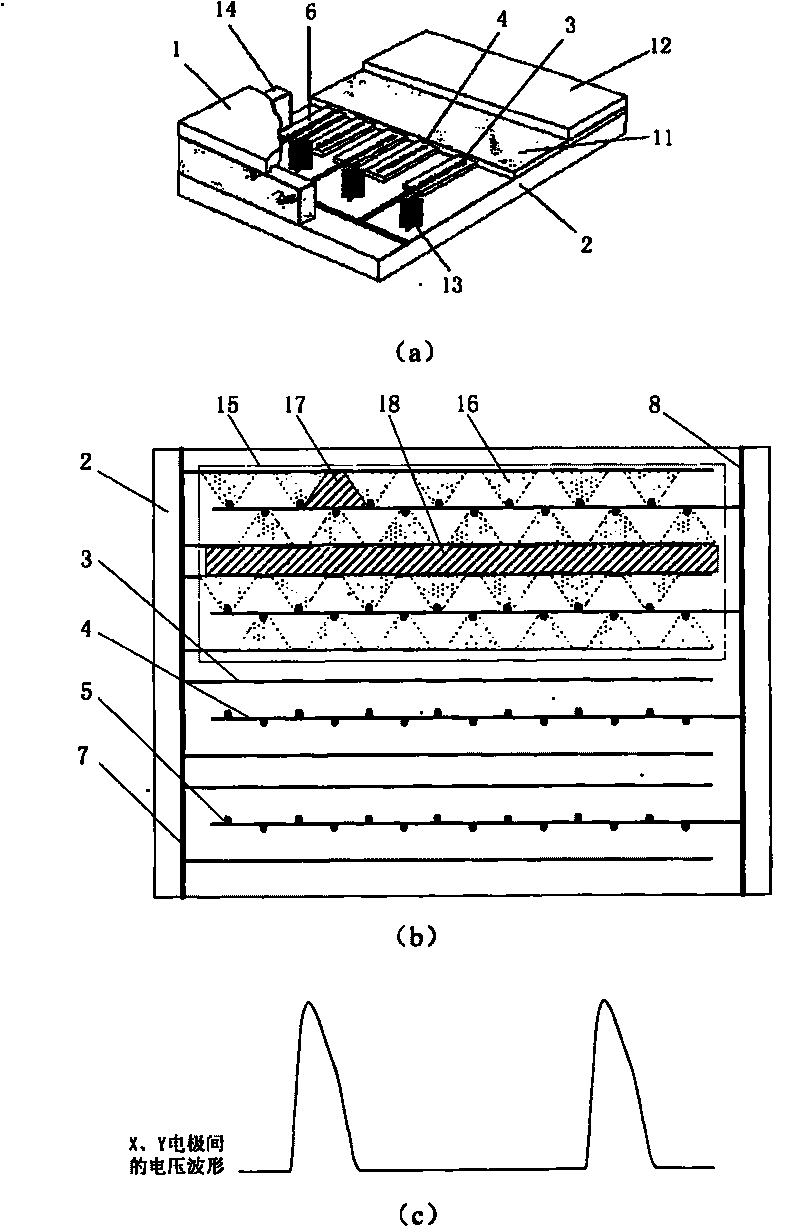
[0033] figure 2 It is the top view and driving voltage waveform diagram of the flat fluorescent lamp of the present invention. The flat fluorescent lamp includes a front glass substrate 1 and a rear glass substrate 2, the inner surface of the front glass substrate 1 is covered with a phosphor layer, and the inner surface of the rear glass substrate 2 is provided with two sets of strip electrodes——X electrodes 3 and Y electrodes 4, Protrusions 5 with a certain interval are arranged on the side of the Y electrode 4, the X electrode 3 and the Y electrode 4 are covered with a dielectric layer 6, and the surface of the dielectric layer 6 and the inner side of the rear glass substrate 2 not covered by the dielectric layer 6 are covered. There is a phosphor layer. After the two substrates are aligned, they are sealed together with low-melting glass around them, and the interior is filled with inert gas. All the discharges between the X electrodes 3 and the Y electrodes 4 are divid...


PUM


Abstract

The invention discloses a flat fluorescent lamp, which comprises a front glass substrate and a back glass substrate, the inner side of the front glass substrate is provided with a phosphor layer, while the inner side of the back glass substrate is provided with electrodes, a media layer and a phosphor layer. The strip-typed electrodes are divided into two groups and are arranged in parallel, the side of one group of the electrodes is provided with a plurality of processed distributed at regular intervals which positions and seals the front substrate and the back substrate, and then inert gas is filled. The neighboring luminous rows of the invention adopt alternating discharge and the splicing of two groups of alternating discharging regions, reducing or removing the non-luminous region between the neighboring luminous rows and between the neighboring micro-discharge, thus increasing the brightness and the brightness uniformity of the flat lamp.

Description

technical field [0001] The invention belongs to the field of display and lighting source manufacturing, and relates to a fluorescent lamp, in particular to a plane fluorescent lamp which can be used as a liquid crystal display backlight source and a common lighting source. Background technique [0002] In recent years, with the further maturity of production technology and the continuous reduction of manufacturing costs, large-screen liquid crystal displays (LCDs) have been more and more widely used. Flat-panel liquid crystal displays with large information capacity are generally transmissive, requiring a light source behind the liquid crystal panel to realize display. At present, the backlight commonly used in flat-panel liquid crystal displays is a cold cathode fluorescent lamp (CCFL), which has the advantages of high light efficiency and brightness, but its disadvantages are that it takes a long time to reach saturated brightness after lighting, and the ignition is greatl...

Claims


Application Information

Patent Timeline
Patent Type & Authority Patents(China)
IPC IPC(8): H01J61/06H01J61/00
Inventor 胡文波徐伟军丁兴隆唐李晟郑德修刘震
Owner XI AN JIAOTONG UNIV
Why Eureka
Try Eureka