Height adjustable structure

A height-adjustable and height-adjustable technology, which can be applied to tables that can change the height of the desktop, chairs that can adjust the seat vertically, tables, etc., can solve the problems of occupying space, increasing fatigue, and high costs, reducing the time cost of assembly and reducing health care. The effect of good health and space saving

Inactive Publication Date: 2008-02-06
邱柏森 +1
View PDF0 Cites 6 Cited by
  • Summary
  • Abstract
  • Description
  • Claims
  • Application Information

AI Technical Summary

Problems solved by technology

But this is not only expensive, but also in the small living space of modern cities, it may not be able to accommodate the exclusive furniture of each family member
[0005] In addition, various home appliances such as TV monitors and computer monitors are indispensable equipment for displaying digital multimedia image data. Since the monitor provides users with visual reception, the most comfortable viewing angle for the human eye is head-up, but because each user's sitting posture When standing or standing, the height and body length are all different. If the height of the monitor cannot be adjusted, it will not be able to match the best position of the human eye. Long-term use will not only increase fatigue, but also cause visual impairment
[0006] In view of the above-mentioned furniture and home appliance products, because it is impossible to adjust the appropriate height for each user’s height and body length, some manufacturers in the market have added height adjustment devices to furniture and home appliances. In order to conform to ergonomics and improve the comfort of individual users
[0007] However, the above-mentioned height adjustment devices for furniture and home appliances are not only complicated in structure, difficult to assemble, but also expensive, easy to damage, and generally accepted by the market. , for modern urban families where every inch of land is expensive, it will cause even greater inconvenience

Method used


Image

  • Height adjustable structure
  • Height adjustable structure
  • Height adjustable structure

Examples


Embodiment Construction

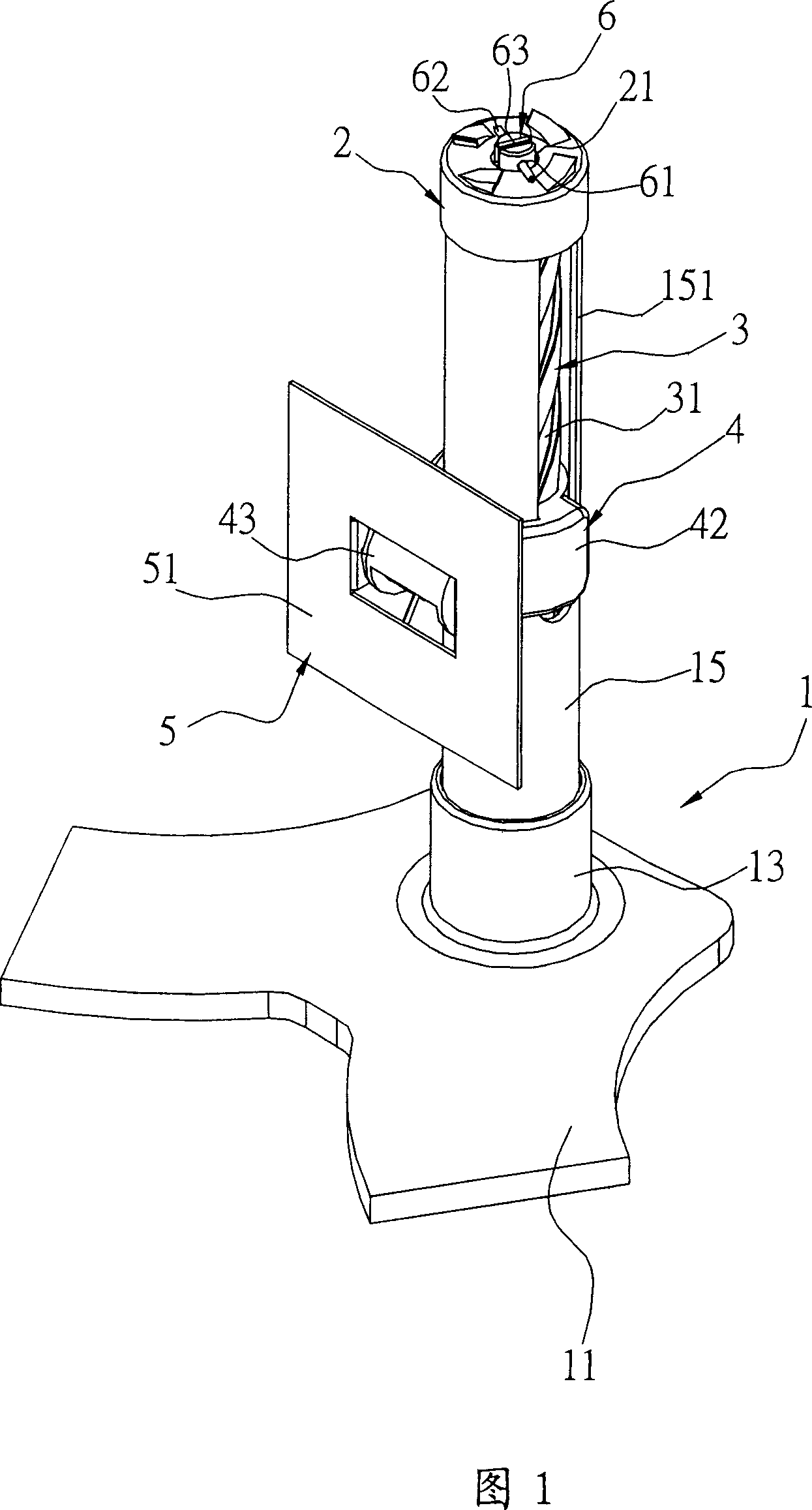
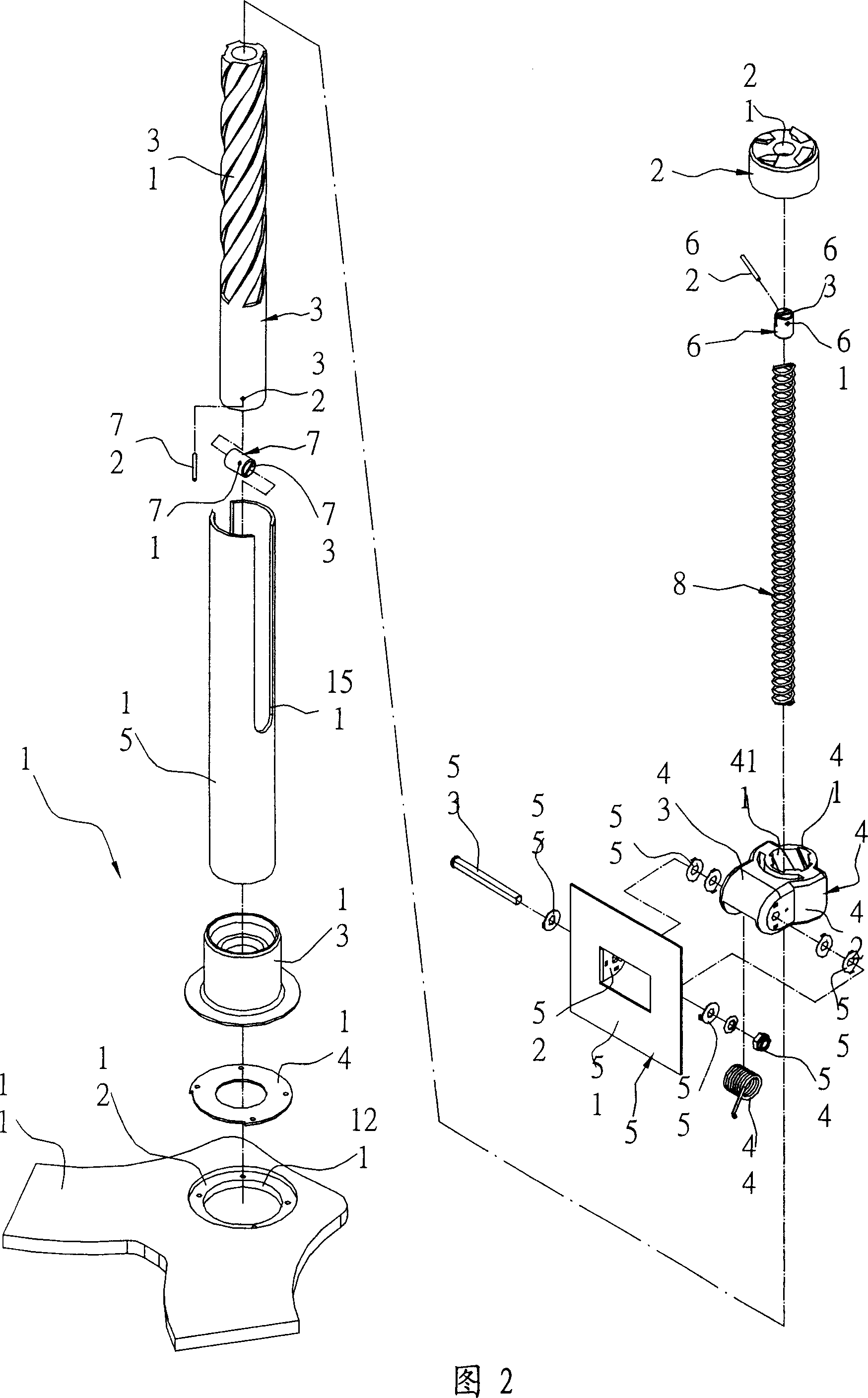
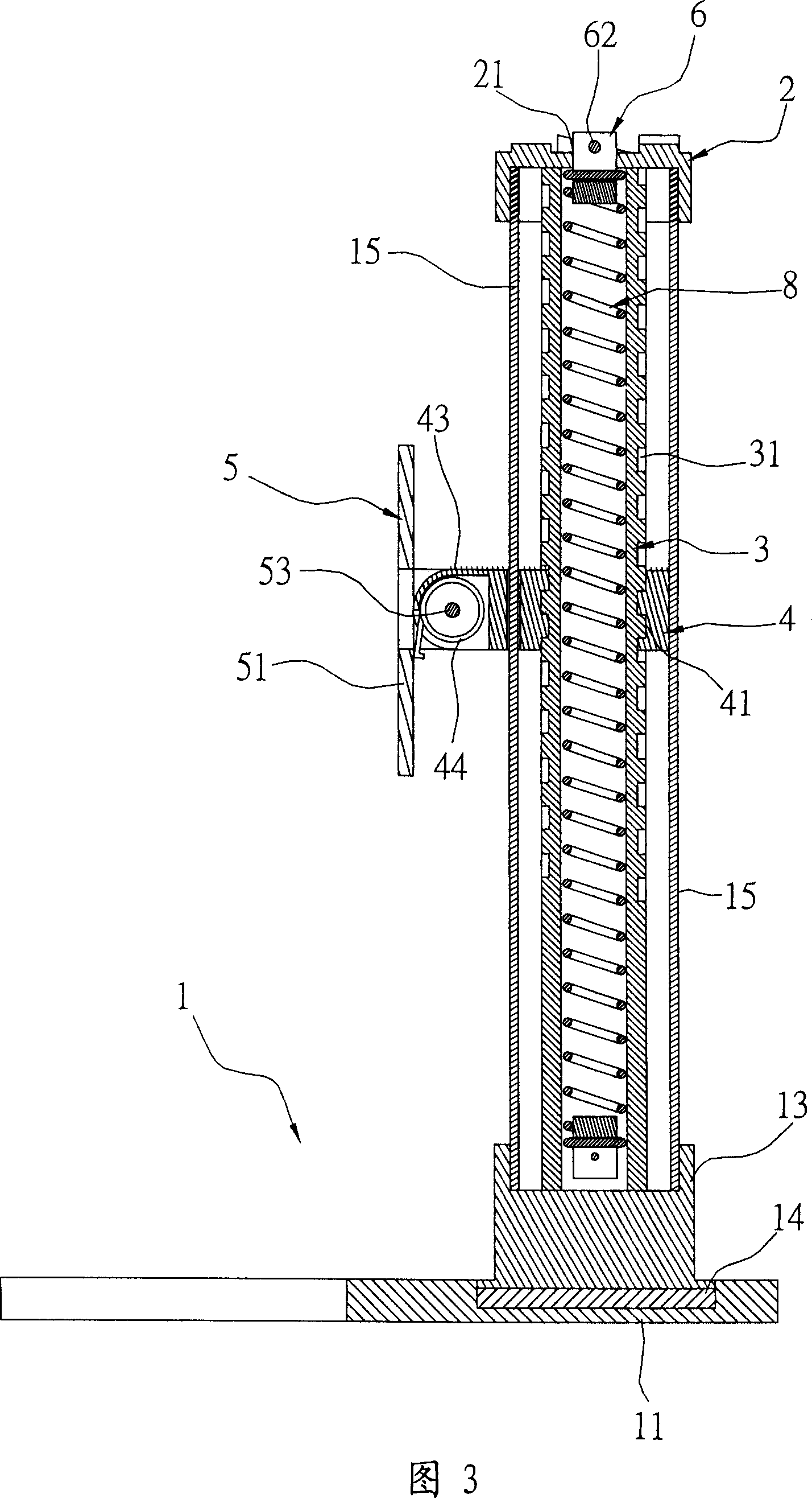
[0056] First, please refer to Fig. 1, Fig. 2 and Fig. 3, the present invention includes: a supporting body 1, a coaxial block 2, a shaft tube 3, a sliding seat 4, a first positioning block 6, a second The positioning block 7 and a torsion unit 8 are formed. Wherein, the supporting body 1 has a bottom plate 11, a shallow groove 12 is opened on the bottom plate 11, and a through hole 121 is opened at the bottom of the shallow groove 12, and a set of seats 13 is arranged on the bottom plate 11 and fixed in the shallow groove 12. , and the first gasket set 14 is provided between the sleeve 13 and the shallow groove 12, and a housing body 15 is fixed on the sleeve 13, and the housing body 15 is in the shape of a circular tube, and the housing body 15 is a A sliding groove 151 with a height difference is provided on the two side walls of the diameter respectively.

[0057] The coaxial block 2 seals the top end of the accommodating body 15 , and defines a through hole 21 on the coax...


PUM


Abstract

A height adjustment structure which supports an object and adjusts the object height comprises a supporter, a container, a sliding chute with different height, a coaxial block, a shaft tube, a spiral track, a slider, a spiral combination part, a restriction arm and a twisting unit. The supporter is provided with at least one container. The sliding chute with different height is arranged on at least one side of the container. The coaxial block is closely arranged on the top of the container. The spiral track is formed on the surface of the shaft tube which is arranged inside the container. The slider is also arranged in the container, and is sleeved with the shaft tube. A spiral combination part, which is formed on the edge of the slider inside, exactly corresponds to the spiral track. The restriction arm which extends out of the sliding chute is arranged on at least one side of the slider. The twisting unit is encased inside the shaft tube, and the two ends of the unit are fixed on the coaxial block and the shaft tube separately. The height is adjusted through making the slider support the object and using the sliding of the slider along the sliding chute in the container.

Description

technical field [0001] The invention relates to a height adjustment structure, in particular to a height adjustment structure which is easy to assemble, saves components and is easy to operate. Background technique [0002] Human beings are a kind of living organism. Due to the different genes and growth environment of each person, there are inherent differences in height. In particular, human height is not static, but will gradually increase over time or shrink slightly due to aging. However, all kinds of furniture such as tables, chairs or counters in life have been designed to be non-adjustable in height since the early days. Although the manufacturer can pre-plan and produce a variety of specifications and models of different heights when producing the above-mentioned furniture, as far as possible to meet the height and body length of the user, in order to make each user with different height and body length feel comfortable and meet ergonomics. However, this is not th...

Claims


Application Information

Patent Timeline
Patent Type & Authority Applications(China)
IPC IPC(8): A47B9/00A47C3/20
Inventor 邱柏森颜清辉
Owner 邱柏森
Why Eureka
Try Eureka