
Method for marking on glass by YAG laser

A technology on YAG laser and glass, which is applied in the field of YAG laser marking on glass. It can solve the problems of not being able to meet the requirements of marking, the high price of the whole machine equipment, and the deterioration of marking effect, so as to achieve beautiful marking effect and filling effect. Smooth, fast marking effect

Active Publication Date: 2008-02-06
HANS LASER TECH IND GRP CO LTD
View PDF0 Cites 12 Cited by
  • Summary
  • Abstract
  • Description
  • Claims
  • Application Information

AI Technical Summary

Problems solved by technology

However, it basically does not absorb YAG (1064nm) laser, so it is difficult to use YAG laser for direct processing
[0003] The thermal conductivity of glass is very poor. When the laser is applied, due to the small processing area, high thermal stress will be generated along the processing route, causing cracks or shattering of the material.
The linear expansion coefficient of glass is relatively large, so it is easier to break
Therefore, if CO2 laser (10.64μm) is used to process glass, irregular cracks will occur after the surface glass is damaged, which will make the marking effect worse (such as irregular edges, surface burrs, etc.), and basically cannot meet the marking requirements. At present, only the dot matrix effect can basically meet the marking requirements of some industries
[0004] The marking system using ultraviolet (355nm) and deep ultraviolet (266nm) lasers has a very good effect on glass processing, but due to the current problems of slow speed, low power, high price of complete equipment, and complicated maintenance, it is limited Application and promotion

Method used


Image

  • Method for marking on glass by YAG laser
  • Method for marking on glass by YAG laser
  • Method for marking on glass by YAG laser

Examples


Embodiment Construction

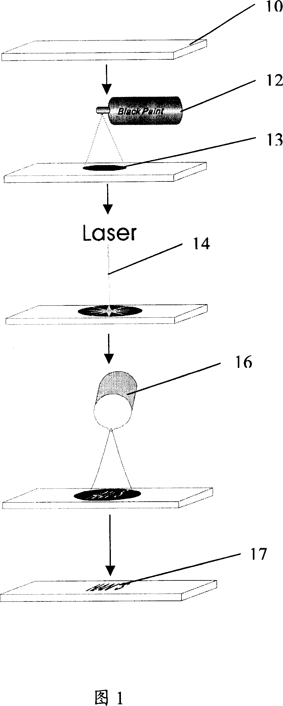
[0023] With the current state of the art, the bottleneck in the application of YAG laser marking on glass is how to improve the absorption rate of the glass surface. On the one hand, it is necessary to increase the single-point pulse energy of the laser. Lamp-pumped laser marking machines (such as YAG-T50 or YAG-T80 from Han’s Laser) use lenses with smaller multiples (such as f=80mm, f=100mm focusing lens); on the other hand, The glass surface needs to be treated to increase the absorption rate.

[0024] We first experiment with YAG-T50,

[0025] Method 1: Use a black water-based marker to paint on the glass surface

[0026] Since the adhesion of the water-based ink is not very strong, after the laser is irradiated, the coating is knocked off, and the glass will not absorb the laser when the second time is applied, but after cleaning the glass, it can be found that there is a faint mark of the laser left. The glass surface, although not clear, has achieved the function of ma...


PUM


Abstract

The invention discloses a method of marking on a glass with YAG laser. The steps of the invention is that: first, a glass needed to be marked is chosen; second, a position needed to be marked on the glass by alignment is sprayed with black paint or black ink; third, lasers emitted by the YAG laser are used to mark on the position needed to be marked on the glass; fourth, the marked position is cleaned by means of cleaning fluid. The invention can increase the absorptivity of glass surfaces to near infrared laser and will greatly accelerate the application of the YAG laser on the glass industry.

Description

【Technical field】 [0001] The invention relates to a method for marking glass with YAG laser. 【technical background】 [0002] Glass has very good absorption of CO2 laser (10.64μm), ultraviolet (355nm), deep ultraviolet (266nm) laser, and is more suitable for glass processing. However, it basically does not absorb YAG (1064nm) laser, so it is difficult to use YAG laser for direct processing. [0003] The thermal conductivity of glass is very poor. When the laser is applied, due to the small processing area, a high thermal stress will be generated along the processing route, which will cause the material to crack or shatter. The coefficient of linear expansion of glass is relatively large, so it is easier to break. Therefore, when CO2 laser (10.64μm) is used to process glass, irregular cracks will occur after the surface glass is damaged, which will make the marking effect worse (such as uneven edges, surface burrs, etc.), which basically cannot meet the marking requirements....

Claims


Application Information

Patent Timeline
IPC IPC(8): C03C23/00
Inventor 高云峰高元
Owner HANS LASER TECH IND GRP CO LTD
Learn More