Fiberglass insulating tube with multi-layer ring shaped braiding structure

A technology of circular braiding and fiberglass, which is applied to the shape/style/structure of winding insulation, insulators, insulators, etc., can solve the problems of low production efficiency, low dimensional accuracy, and increased costs, and achieve improved manufacturing efficiency, simple production process, The effect of cost reduction

Inactive Publication Date: 2008-02-06
郝跟进
View PDF1 Cites 20 Cited by
  • Summary
  • Abstract
  • Description
  • Claims
  • Application Information

AI Technical Summary

Problems solved by technology

Although this method can meet the production needs of the motor, it has the following disadvantages: (1), the material needs to be transported back and forth, which increases the cost and wastes time: (2), this method is to press the BMC group material onto the shaft and the silicon steel sheet In the middle, each product needs to be cured for 2-3 minutes, and the production efficiency is low: (3) When recompressing, if the position of the shaft and the silicon steel sheet deviates, the motor is prone to vibration during rotation, which makes the product unqualified and the scrap rate is high
The pultrusion winding method is based on the pultrusion method, and the longitudinal reinforcing fibers are hoop-wound while pultruding, and then solidified by heating the mold. The FRP insulating pipe produced by this method has increased longitudinal and hoop Strength, but because the longitudinal reinforcement fibers and the hoop reinforcement fibers are only superimposed, and there is no cross-braiding between fibers, the torsional strength is low
Patent 03138047.6 discloses a production method of pultruded pipes. Although the overall strength of the FRP insulating pipe produced by this method is strengthened, it has the following disadvantages: (1) Low production efficiency and high cost. The main reinforcement layer is woven on the machine, and then the inner and outer surface layers of the main reinforcement layer and the long fiber reinforcement layer are passed through the preforming die for pultrusion molding, which requires secondary production and low efficiency
At the same time, the main reinforcement layer, the inner and outer surface layers, and the long fiber layer are impregnated and pultruded through the mold at the same time, the resin is difficult to penetrate, and the product strength is low
(2) The precision is low and the thickness of the product is uneven. The inner and outer surface layers of this method are a kind of braid wrapped into a circular structure. If the width of the braid is smaller than the circumference of the garden, the reinforcing fibers cannot overlap each other to form a If there is a gap, the reinforcing layer has no effect. If the width of the braid is larger than the circumference, the fiber fabrics will overlap each other, and the product at this place will be thicker than other places.
(3) The strength is low, and the circular interface between the inner and outer surface layers is only bonded by resin, and the fibers are not integrated, so the high tensile properties of the fibers cannot be exerted
(4) In this method, the inner mold adopts a tapered circular tube, and the diameter of each reinforcing layer becomes smaller as it is pulled, so that the reinforcing fibers cannot be fully stretched, the fiber prestressing effect is lost, and the dimensional accuracy in the tube is low
(5) The FRP insulating pipe is only suitable for FRP conveying fluid media or anti-corrosion lined pipelines, especially oil pipes and high-pressure water injection pipes for oil fields, but it cannot meet the needs of micro-motors with higher strength requirements

Method used


Image

  • Fiberglass insulating tube with multi-layer ring shaped braiding structure
  • Fiberglass insulating tube with multi-layer ring shaped braiding structure

Examples


Embodiment 1

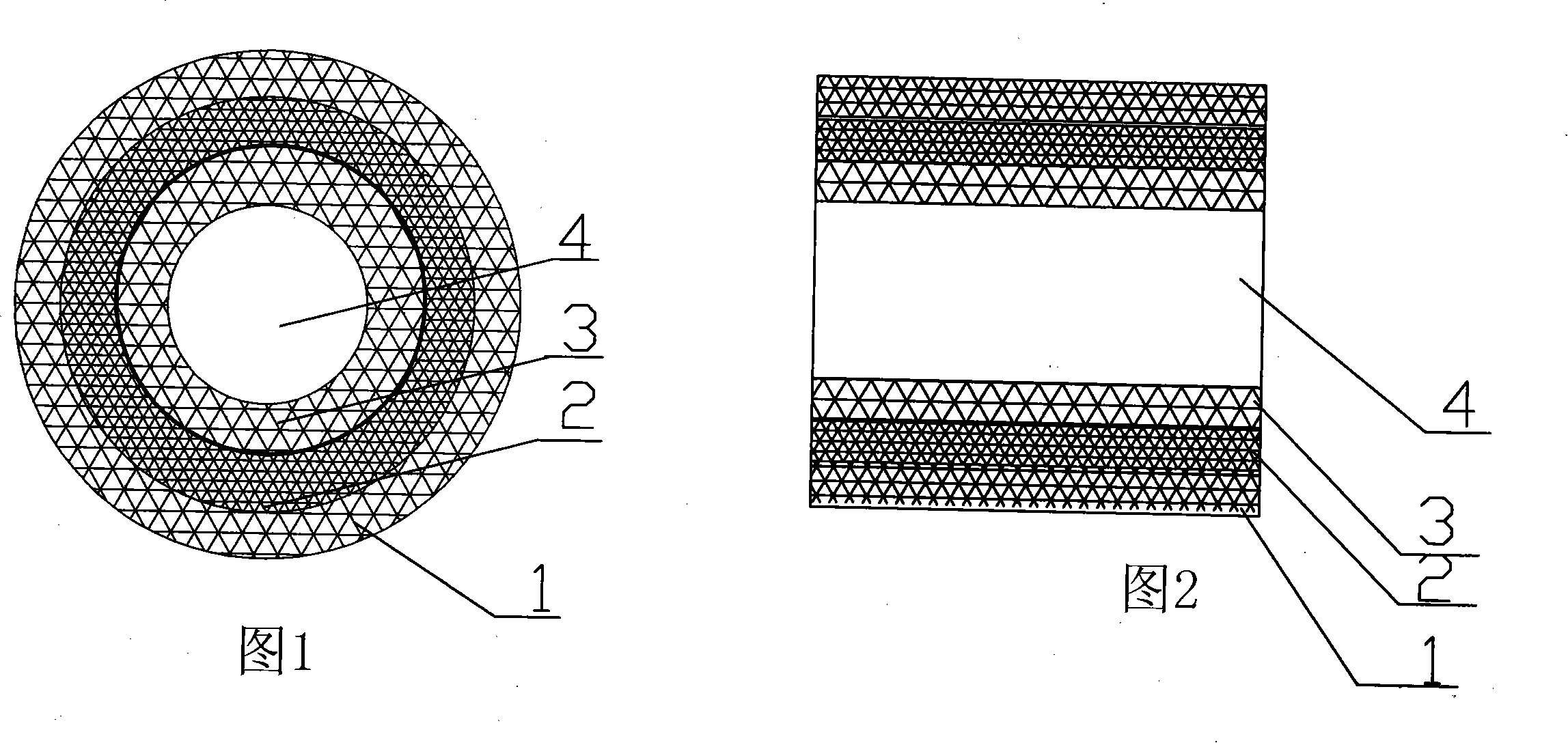
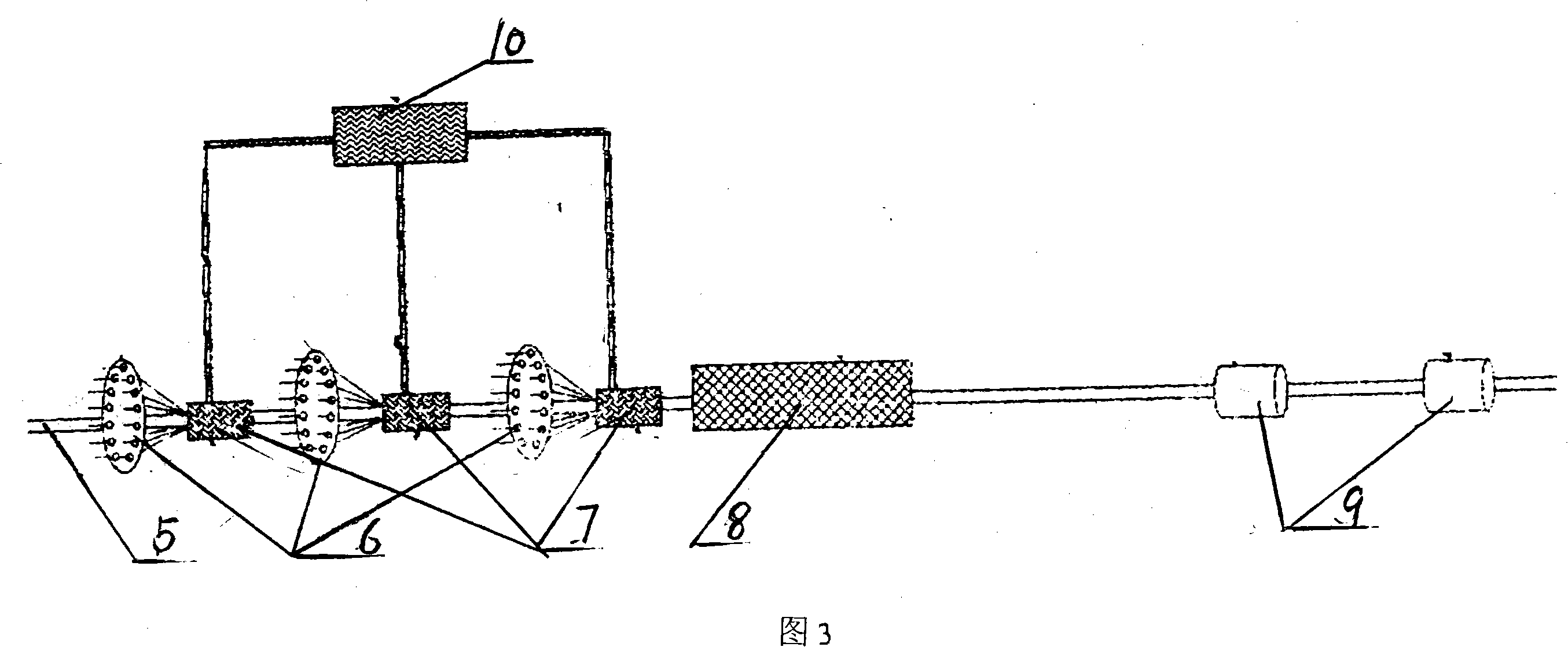
[0022] As can be seen from Fig. 1 and Fig. 2: the multi-layer FRP insulating pipe 4 is composited by three layers of FRP insulating pipes (1, 2, 3), and each layer of FRP insulating pipe of the composite FRP insulating pipe is It is a fiberglass insulated braided pipe circularly braided by warp and weft on a horizontal knitting machine. The diameter of the composite fiberglass insulated pipe can be between 2 and 600 mm. It can be seen from Figure 3 that each layer of fiberglass insulated braided pipe is composited The fiberglass insulating braided pipe impregnated with the adhesive before, and the composite fiberglass insulating pipe are compounded under the same uniform straight mandrel, and finally shaped and solidified by the pultrusion die to form the fiberglass insulating pipe.

[0023] It can also be seen from Fig. 3 that the present invention adopts three computer-controlled two-dimensional horizontal braiding machines 6 to circularly weave three layers of fiber braided ...


PUM


Abstract

The present invention discloses a glass steel insulating tube with the multi-layer round structure, which is compounded with the multi-layer glass steel insulating tube, each glass steel insulating tube of the compounded glass steel insulating tube is the glass steel insulating weaving tube which is weaved at the moving type core tube by the horizontal knitting machine, each layer of the lass steel insulating weaving tube is dipped by the bond before the compound; the compounded glass steel insulating tube is compound under the same straight core mould, and finally shape and solidified by a pulling mould; the glass steel insulating tube is formed by the 2 to 5 layers of the glass steel insulating weaving tube. Compared with prior compound tube, the intensity and the accuracy of the glass steel insulating tube are improved greatly, the thickness of the tube wall only differ from 1 to 2 threads, in particular to the application of the micro electromotor double insulating tubes make the manufacture efficiency of the micro electromotor improve, and the cost is reduced, and the production craftwork is simple.

Description

Technical field: [0001] The invention relates to a glass fiber reinforced plastic insulating tube, which is mainly used for the glass fiber reinforced plastic insulating tube with a multi-layer annular braiding structure in electric tools and micro-motors of household appliances. Background technique: [0002] The current micro-motor manufacturers all use the micro-motor rotating shaft and silicon steel sheet to be sent to professional manufacturers, and the professional manufacturer uses BMC lumps to compress the middle of the rotating shaft and silicon steel sheet, make an insulating layer after curing, and then return to the factory for assembly. Although this method can meet the production needs of the motor, it has the following disadvantages: (1), the material needs to be transported back and forth, which increases the cost and wastes time: (2), this method is to press the BMC group material onto the shaft and the silicon steel sheet In the middle, each product needs t...

Claims


Application Information

Patent Timeline
Patent Type & Authority Applications(China)
IPC IPC(8): H02K3/30H02K3/32H02K3/34H01B17/58
CPCH01B17/325
Inventor 郝跟进
Owner 郝跟进
Why Eureka
Try Eureka