Automatic control of a medical device

A technology of medical equipment and equipment, applied in the field of automatic activation and deactivation systems, to achieve the effect of improving accuracy

Inactive Publication Date: 2008-02-06
KONINKLIJKE PHILIPS ELECTRONICS NV
View PDF0 Cites 57 Cited by
  • Summary
  • Abstract
  • Description
  • Claims
  • Application Information

AI Technical Summary

Problems solved by technology

Therefore, such monitoring should not be permitted if it is not performed by an operator

Method used


Image

  • Automatic control of a medical device
  • Automatic control of a medical device
  • Automatic control of a medical device

Examples


Embodiment Construction

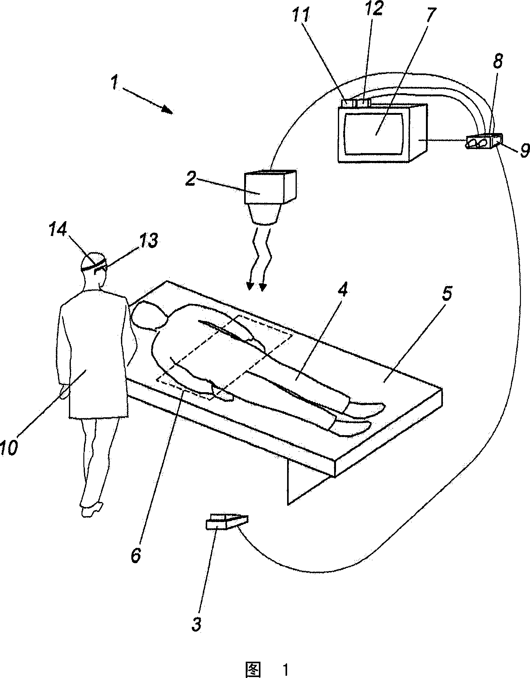
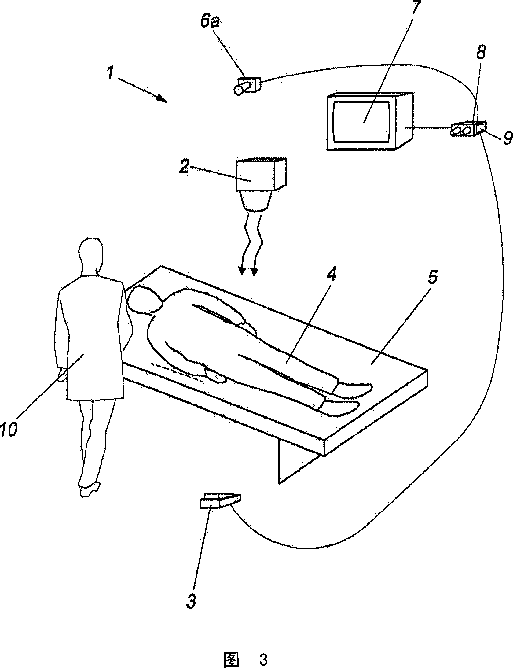
[0107] The system 1 according to the invention comprises an element 2 emitting ionizing radiation, such as X-rays, fluoroscopy or the like.

[0108] The emission of radiation by the element 2 is usually controlled by an emission control unit comprising a pedal 3 or switch, which is depressed by the operator. As long as the pedal is depressed, the emission of radiation occurs, and vice versa.

[0109] In the case of obtaining a radiographic image, the radiation beam is directed towards the patient 4, usually lying in a stretcher 5 compartment, and the radiation beam then encounters the element 6, which is sensitive to the radiation. As the radiation beam passes through the patient's body, the absorption that occurs results in the formation of an image, which is picked up by element 6 and transmitted to modality monitor 7 .

[0110] In the case of radiation therapy, the images displayed on the screen are only used for the purpose of verifying that the patient is correctly posit...


PUM


Abstract

An eye tracking system determines the true gazing direction of operator of medical device relative to a monitor, while passing radiations through the body of the patient (4). An evaluation device evaluates the determined gazing direction of the operator (10). The activation or deactivation of a pedal or switch (3) is controlled automatically corresponding to the evaluation device output. An independent claim is included for the method of automatic control radiation source.

Description

technical field [0001] The present invention relates to a system and method for automatic activation and deactivation of radiation sources for medical purposes. The present invention also relates to a system and method for automatically activating and deactivating ionizing radiation controlled by operator gestures and / or gestures. The present invention also relates to a system and method for automatic control through gaze processes or applications that require visual attention or monitoring. Background technique [0002] Currently, in radiological investigations involving interventions to activate ionizing radiation manipulations (such as X-rays and fluoroscopy, etc.) switch) depressed, these pedals are usually located on the floor under the operating table, the operating table can be covered by sheets and plastics, etc., which cover the patient and the operating table, thereby blocking the image under the operating table Vascular, cardiovascular, digestive, CAT, traumatol...

Claims


Application Information

Patent Timeline
Patent Type & Authority Applications(China)
IPC IPC(8): A61B6/00
CPCA61B6/00H05G1/56H05G1/58
Inventor M·弗男德茨古尔雷罗S·邦菲格利奥J·克拉默F·马特加尼
Owner KONINKLIJKE PHILIPS ELECTRONICS NV
Why Eureka
Try Eureka