Woodworking machine comprising a linear direct drive
What is Al technical title?
Al technical title is built by PatSnap Al team. It summarizes the technical point description of the patent document.
A technology of woodworking machine tools and driving devices, which is applied in the direction of electromechanical devices, sawing devices, feeding devices, etc., and can solve the problems of high cost of magnets, mechanical wear of mechanical transmission units, and reduced processing speed.
Inactive Publication Date: 2008-02-06
SIEMENS AG
View PDF0 Cites 13 Cited by
Summary
Abstract
Description
Claims
Application Information
AI Technical Summary
This helps you quickly interpret patents by identifying the three key elements:
Problems solved by technology
Method used
Benefits of technology
Problems solved by technology
These mechanical transmission units are subject to mechanical wear and thus require intensive maintenance, repair or replacement if necessary
[0003] Contamination due to machining residues (e.g. chips or dust) and aggressive machining environments (e.g. residual lubricants, adhesives or sealing materials) can also significantly reduce the achievable precision and the achievable machining speed
[0004] As far as conventional drive technology is concerned, known linear motors have gradually taken a backseat in terms of application due to the susceptibility to interference of the external measuring systems they require and the unfavorable economic properties of their linear drives (e.g. high cost of magnets)
The main obstacle lies in the long travel distances of woodworking machines and the resulting high cost of linear drive systems
Method used
Image
Click on the blue label to locate the original text in one second.
Reading with bidirectional positioning of images and text.
Examples
Embodiment Construction
[0080] Before describing in detail the woodworking machine tool with a linear direct drive device, the working mode and feasible implementation of the linear direct drive device (hereinafter also referred to as "motor" or "linear motor") related to the woodworking machine tool will be introduced.
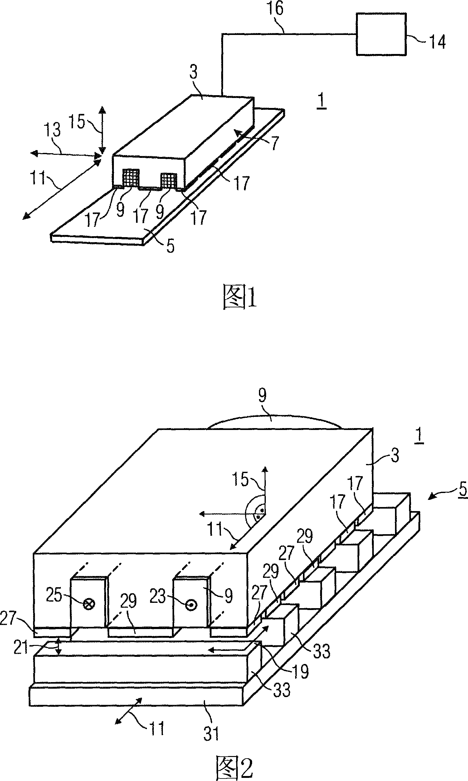
[0081] FIG. 1 shows an electric motor 1 . The electric machine 1 has a primary part 3 and a secondary part 5 . The primary part 3 has a winding 9 and a plurality of permanent magnets 17 . The direction of movement of the primary part 3 is indicated by a double-headed arrow extending in the longitudinal direction 11 . Another double-headed arrow indicates the lateral direction 13 . A third double-headed arrow indicates the normal 15 , wherein the normal relates to an air gap plane 19 not shown in FIG. 1 . However, the air gap plane 19 is shown in FIG. 2 . The arrows point to the side view 7 referring to what is shown in FIGS. 3 and 4 . The electric machine 1 is a linear motor th...
PUM
Abstract
The aim of the invention is to provide a robust, simple woodworking machine. To achieve this, the invention provides a machine comprising at least one linear direct drive, which contains a primary part (3, 3a, 3b, 4, 4a, 4b) with a first element (9, 10, 12, 14) for generating a first magnetic field and at least one additional element (17, 18, 20, 27, 28, 29, 30) for generating an additional magnetic field. The first element (9) for generating the first magnetic field is positioned, in particular, in such a way in relation to the additional element (17, 18, 20, 27, 28, 29, 30) for generating the additional magnetic field that the first magnetic field overlaps the additional magnetic field. The machine also comprises a secondary part (5, 6, 6a, 6b), which comprises magnetic return elements and is devoid of magnetic sources. According to the invention, the primary part (3, 3a, 3b, 4, 4a, 4b) and / or the secondary part (5, 6, 6a, 6b) is or are suitable for guiding or placing at least one workpiece and / or for guiding and / or placing at least one tool for machining the workpiece.
Description
technical field [0001] The invention relates to a woodworking machine tool having at least one linear direct drive having a primary part and a secondary part. Background technique [0002] A large amount of linear motion occurs on a woodworking machine tool. For example, workpiece transport and workpiece processing, tool feeding and auxiliary material supply have hitherto been realized with conventional drive technology and mechanical transmission units such as transmissions, pinions engaging racks and ball screws. These mechanical transmission units are subject to mechanical wear and thus require intensive maintenance, repair or replacement when necessary. [0003] Contamination due to machining residues (e.g. chips or dust) and aggressive machining environments (e.g. residual lubricants, adhesives or sealing materials) can also significantly reduce the achievable precision and the achievable machining speed. [0004] As far as conventional drive technology is concerned, ...
Claims
Application Information
Patent Timeline
Application Date:The date an application was filed.
Publication Date:The date a patent or application was officially published.
First Publication Date:The earliest publication date of a patent with the same application number.
Issue Date:Publication date of the patent grant document.
PCT Entry Date:The Entry date of PCT National Phase.
Estimated Expiry Date:The statutory expiry date of a patent right according to the Patent Law, and it is the longest term of protection that the patent right can achieve without the termination of the patent right due to other reasons(Term extension factor has been taken into account ).
Invalid Date:Actual expiry date is based on effective date or publication date of legal transaction data of invalid patent.