A method for manufacturing cold forming punch pin of screw head with multi-layer groove

A technology for forming heads and screw heads, which is applied in the direction of screws, manufacturing tools, general control systems, etc., and can solve problems such as unbearable and expensive operation costs

Inactive Publication Date: 2008-02-13
UNISCREW
View PDF3 Cites 4 Cited by
  • Summary
  • Abstract
  • Description
  • Claims
  • Application Information

AI Technical Summary

Problems solved by technology

Otherwise, the number of operations and punch cost (for example, if two different punches are required) makes the operation prohibitively expensive;
[0013] 2) For the same reason, the punch must be able to use more than 100,000 times, or similar;
[0014] 3) The manufacture of the punch must be cheap

Method used


Image

  • A method for manufacturing cold forming punch pin of screw head with multi-layer groove
  • A method for manufacturing cold forming punch pin of screw head with multi-layer groove
  • A method for manufacturing cold forming punch pin of screw head with multi-layer groove

Examples


Embodiment Construction

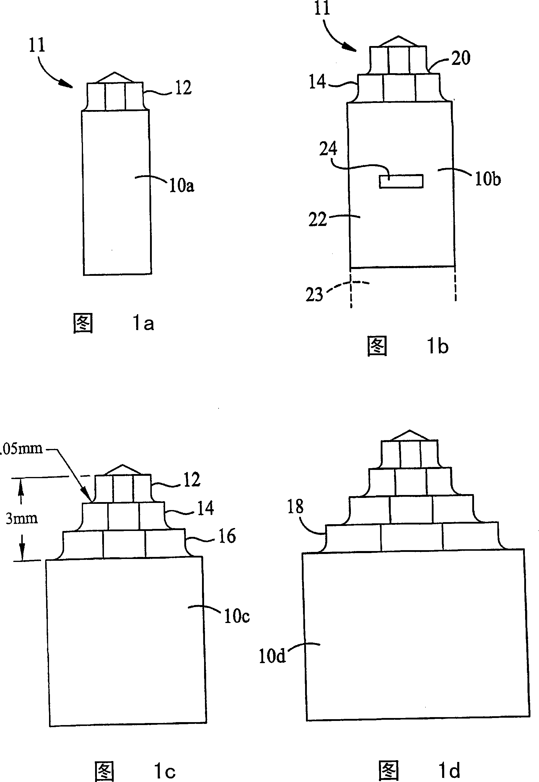
[0051] Referring to FIG. 1 , each figure shows a punch 10a, b, c, d having one, two, three, four layers 12, 14, 16, 18, respectively. The height of each layer is about 1 mm. Each layer has a chamfer at the base for supporting itself. The radius of the chamfer is about 0.05mm. Punch 10 is manufactured from bar stock 22, 23, the head section of which is cut using a forming computer numerically controlled machine tool as will be described further below. When cutting the section 11, the computer numerical control machine tool simultaneously cuts out the positioning groove 24, and cuts off the formed punch 10b and the remaining bar 23.

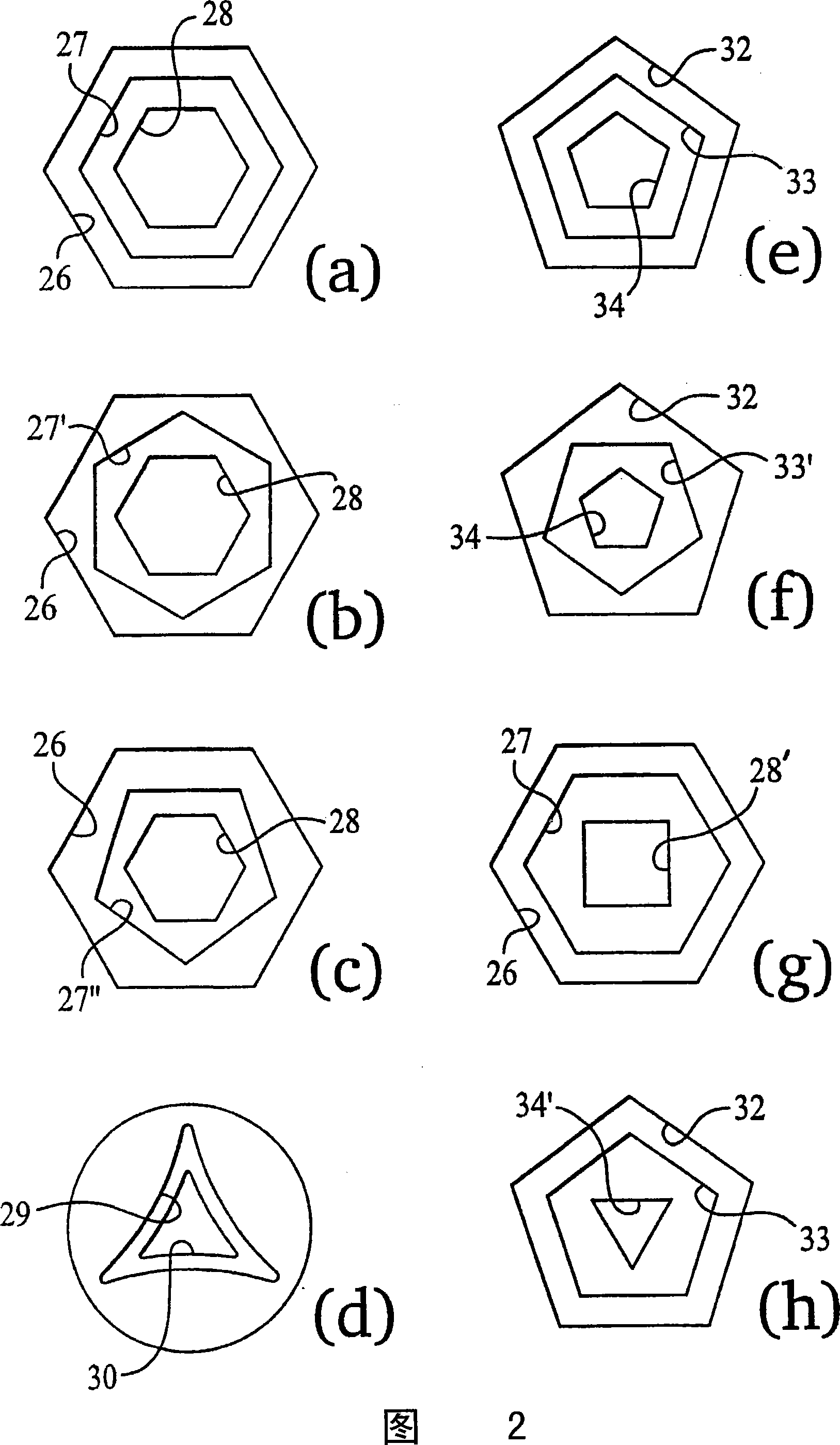
[0052] When the punch 10 is mounted on a cold heading device and driven into the screw head in the axial direction, a groove of the cross-sectional shape shown in FIG. 2 is formed.

[0053] Figure 2a is a three layer groove structure with concentric parallelepipeds 26,27,28. Figure 2b is similar to Figure 2a, except that the central groove 27' ...


PUM


Abstract

The screw has two or three non-circular super-imposed recesses. The depth of each recess is less than 1.2 mm and there is a less than 1 DEG of draw in each recess. The screw head recess is formed using a punch (10) in a cold-heading process. The punch is formed in a profilating CNC machine, cutting the profiles (12,14,16) of the punch to a tolerance of better than +-0.025 mm. A method of manufacture of a cold-forming punch for such a screw comprises providing a profilating head as one of the tools on a turret mounted adjacent the chuck in the CNC machine. The profilating head has several cutting elements, each being adjustable with respect to one another: axially, radially and angularly.

Description

[0001] The patent application for this invention is a divisional case of the invention patent application with the international application number PCT / GB02 / 04088, the international application date is September 10, 2002, the application number 02817813.0 entered the Chinese national phase, and the name is "screw head structure". Application. technical field [0002] The invention relates to a screw head for a screw fastener, and a tool for driving the screw. In particular, the invention relates to a method of manufacturing punches for cold forming such screw heads. Background technique [0003] GB1150382 seems to be the first patent that recognizes the advantages of multi-layer screw head design. It designs a step layer between the deep central groove and the wide top groove, and the sides of the groove are parallel to the central axis of the screw. Such grooves are effective in reducing "eccentricity". Furthermore, the recess in the screw head can be deeper without weake...

Claims


Application Information

Patent Timeline
Patent Type & Authority Applications(China)
IPC IPC(8): B23Q27/00B23C3/00B23C5/24F16B23/00B21K1/46B21K5/20G05B19/18
CPCB21K1/463F16B23/0038G05B2219/45137B21K5/20G05B19/186B23C5/2462A61B17/8615Y02P80/40
Inventor L·A·布罗克斯
Owner UNISCREW
Why Eureka
Try Eureka