Mini self-priming pump
A micro-pump, self-priming technology, applied in the direction of pumps, pumps with flexible working elements, liquid variable-capacity machines, etc., can solve the problems of difficult processing technology, unstable work, short service life, etc. The effect of working stability and improving service life
- Summary
- Abstract
- Description
- Claims
- Application Information
AI Technical Summary
Problems solved by technology
Method used
Image
Examples
Embodiment 1
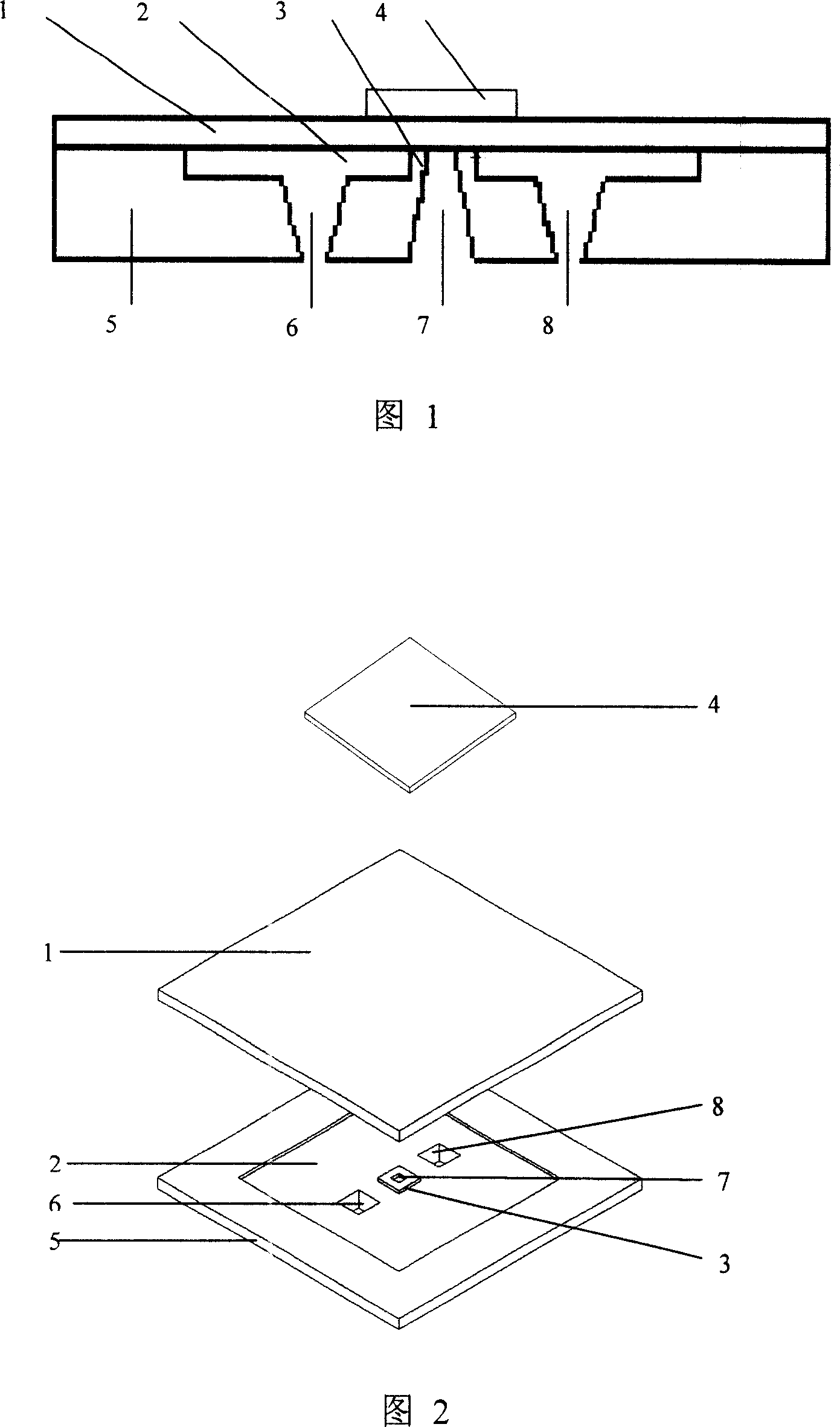
[0027] The first tapered diffuser tube 6 , the tapered constricted tube 7 and the second tapered diffuser tube 8 are all in communication with the pump chamber 2 . The small mouth end of the tapered shrink tube 7 is in contact with the top plate 1 of the pump body, and the tapered shrink tube 7 is normally closed. The large mouth ends of the first tapered diffuser tube 6 and the second tapered diffuser tube 8 are located in the pump chamber 2 and are in a normally open state. The valve seat 3 is located in the middle of the pump chamber 2, and the shape of the pump chamber 2 is square or circular. The small mouth end of the tapered shrink tube 7 is located at the center of the valve seat 3 protruding from the middle of the pump chamber 2 , and the size of the small mouth end of the tapered shrink tube 7 is smaller than that of the valve seat 3 . The height of the upper surface of the valve seat 3 is higher than or equal to the upper surface around the lower plate 5 of the pum...
Embodiment 2
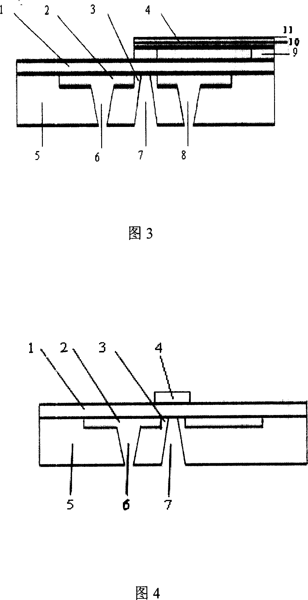
[0029] As shown in Figure 3, it is a piezoelectric-driven single-injection and double-outlet micropump. A tapered shrink tube 6, a tapered diffuser tube 7, a second tapered shrink tube 8, and a driver fixing member 9; the pump chamber 2 adopts a circular or square single cavity, and a single injection port is composed of a tapered shrink tube 7; The first tapered diffuser 6 and the second tapered diffuser 8 form double sample outlets. The lower piece 5 of the pump body is made of silicon wafers; the upper piece 1 of the pump body is a PDMS (polydimethylsiloxane) pump membrane. Wherein, the lower piece 5 of the pump body has a pump cavity 2 , a valve seat 3 , a first tapered diffuser 6 and a second tapered diffuser 8 .
[0030] When an AC voltage is applied to the device, this embodiment can be used as a micropump and self-priming; when a DC voltage is applied to the device, it can be used as a micro valve. The upper part of the pump body 1, the pump chamber 2, the valve seat...
Embodiment 3
[0034] As shown in Figure 4, it is also a single-injection and single-outlet micropump, including the upper piece of the pump body 1, the pump chamber 2, the valve seat 3, the driver 4, the lower piece of the pump body 5, the first conical diffuser tube 6, and the conical constriction tube. Tube 7. There is a tapered diffuser tube 6 and a tapered shrink tube 7 on the lower part of the pump body 5, and the pump chamber 2 adopts a single-chamber structure. Its working principle and geometric dimensions are the same as the example shown in Fig. 3, except that there is one diffuser tube missing.
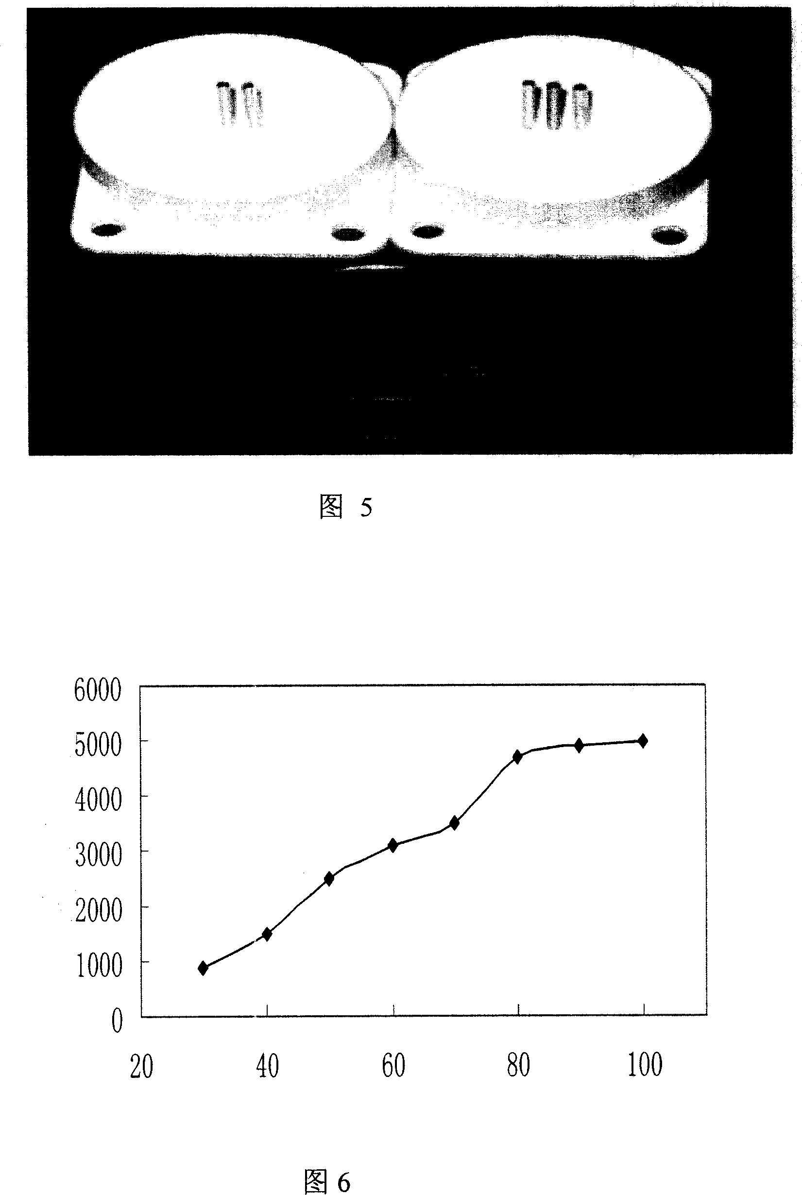
[0035] Fig. 5 is a photo of the micropump of the embodiment.
[0036]Figure 6 is the relationship curve between the flow rate and the driving voltage in Figure 4 of the embodiment. It can be seen from the figure that: under the condition of zero back pressure, when the driving voltage is 100V, the maximum flow rate reaches 5000μL / min, and the flow rate is almost linear with the voltage....
PUM
 Abstract
Description
Claims
Application Information
 - R&D
- Intellectual Property
- Life Sciences
- Materials
- Tech Scout
- Unparalleled Data Quality
- Higher Quality Content
- 60% Fewer Hallucinations
Browse by: Latest US Patents, China's latest patents, Technical Efficacy Thesaurus, Application Domain, Technology Topic, Popular Technical Reports.
© 2025 PatSnap. All rights reserved.Legal|Privacy policy|Modern Slavery Act Transparency Statement|Sitemap|About US| Contact US: help@patsnap.com


