
Red light overriding detection system and method based on digital video camera

A technology of digital cameras and detection systems, applied in road vehicle traffic control systems, traffic flow detection, closed-circuit television systems, etc., can solve problems such as loopholes in law enforcement, high costs, and imprecise laws, and achieve detailed, complete, and economical information. Cost, Ease of Use

Inactive Publication Date: 2008-02-13
TSINGHUA UNIV
View PDF0 Cites 38 Cited by
  • Summary
  • Abstract
  • Description
  • Claims
  • Application Information

AI Technical Summary

Problems solved by technology

[0004] One is high cost
In one direction of an intersection, at least one panoramic camera and close-range cameras or cameras equal to the number of lanes must be installed in order to perform red light detection without missing any blind spots, and the system cost is high
[0005] Second, there are loopholes in law enforcement
Since the license plate information of the violating vehicle cannot be identified in the panoramic camera, there are only clear pictures of the vehicle license plate provided by the close-range camera or the camera, which proves that the violating vehicle in the picture taken by the panoramic camera and the vehicle in the license plate picture are the same vehicle. legal laxity

Method used


Image

  • Red light overriding detection system and method based on digital video camera
  • Red light overriding detection system and method based on digital video camera
  • Red light overriding detection system and method based on digital video camera

Examples


Embodiment Construction

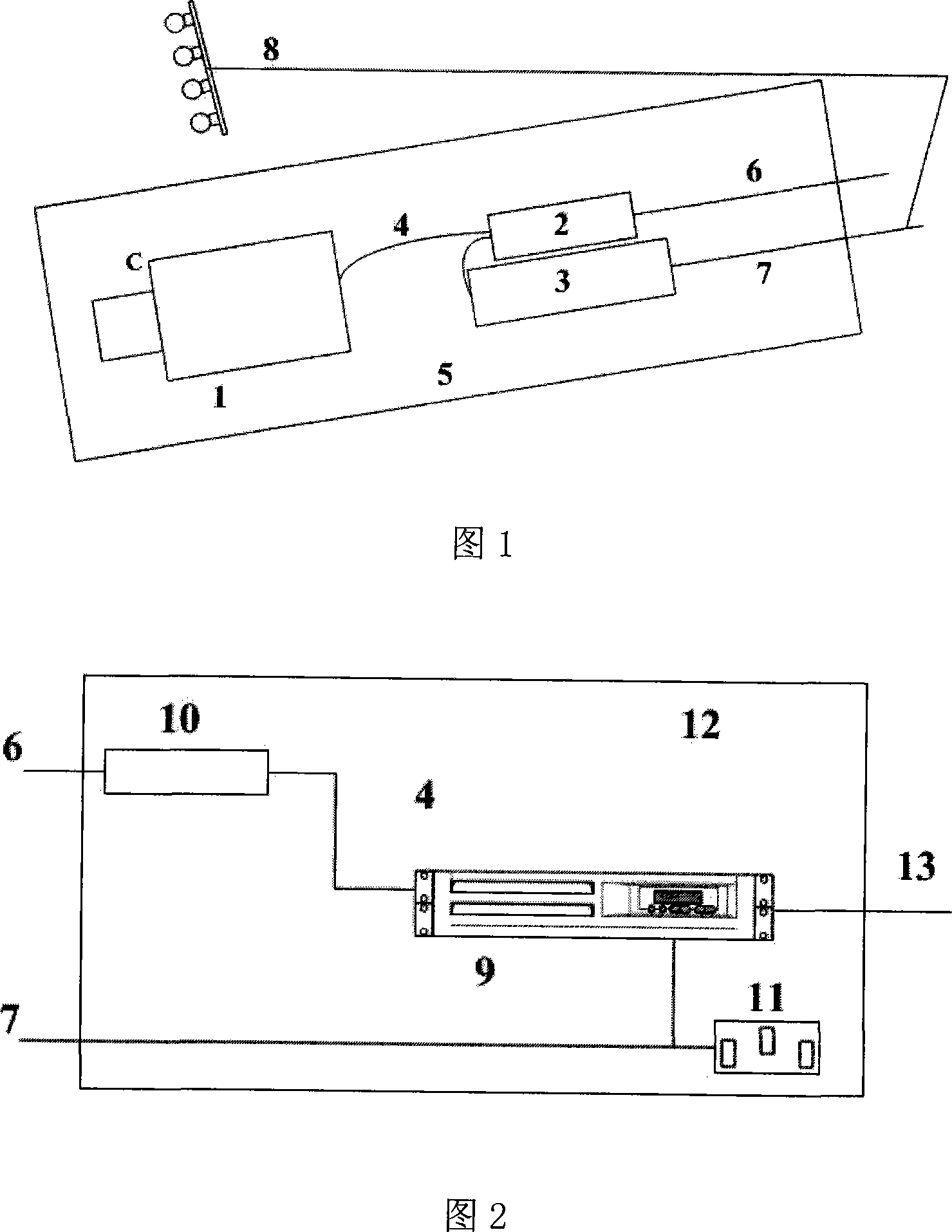
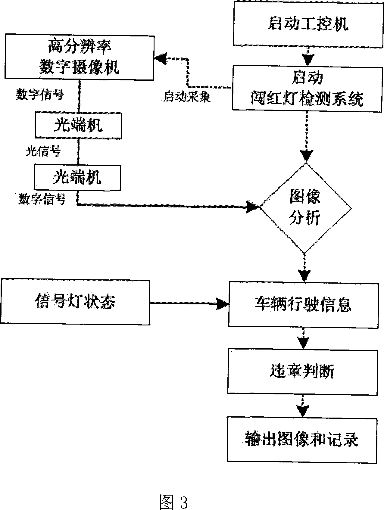
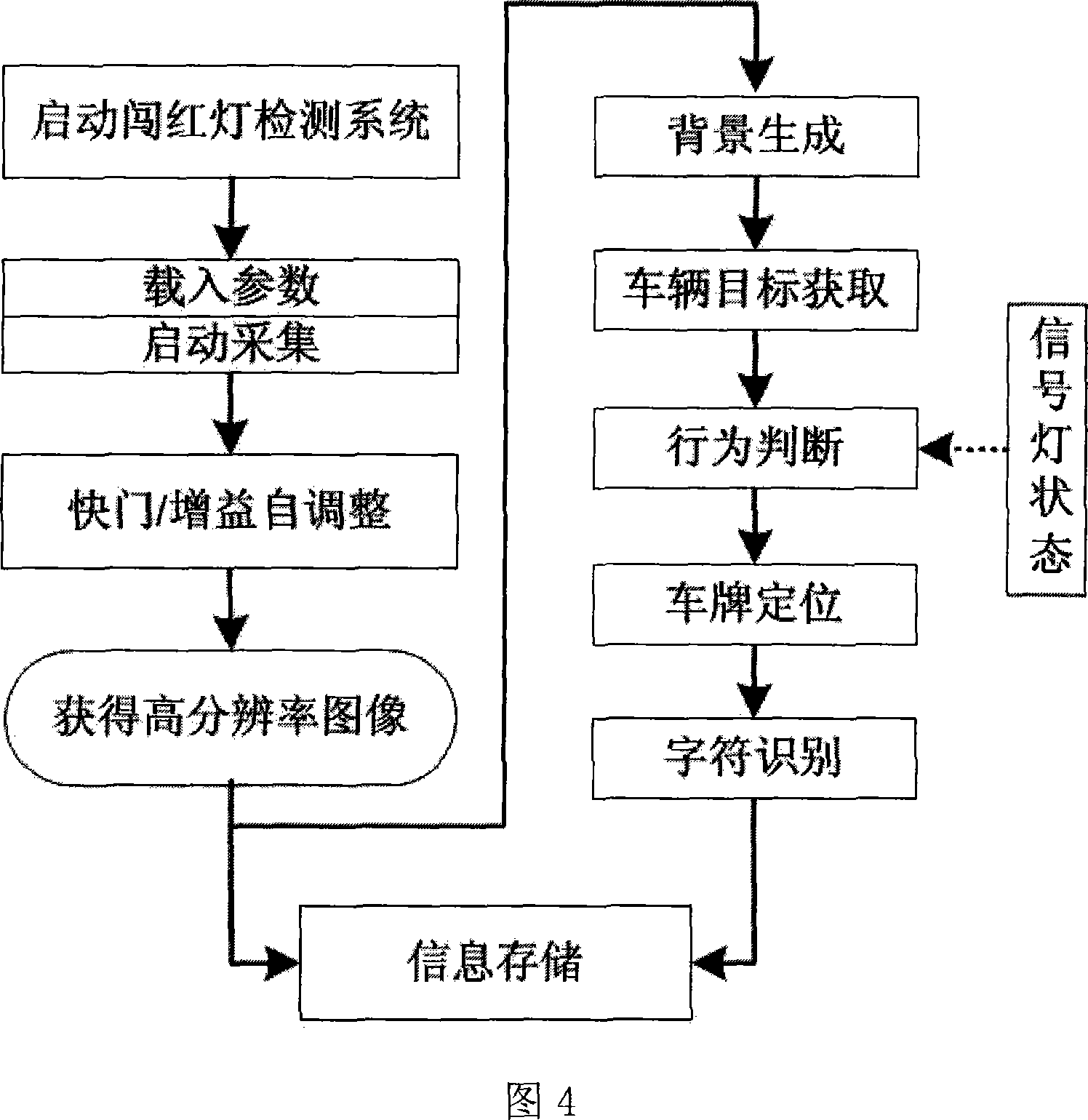
[0042] Hereinafter, this embodiment will be described in detail with reference to FIGS. 1 to 4.

[0043] The red light detection system based on high-resolution digital cameras mainly includes front-end equipment and ground equipment. among them,

[0044] As shown in Figure 1, the front-end equipment includes a pan / tilt, a protective cover 5, a high-resolution digital camera 1 (resolution of 1280*1024) installed in the protective cover, a front-end optical transceiver 2, a regulated power supply 3 (12V), The fill light 8 (infrared light or visible light) and the 1394 adapter cable connecting the camera 1 and the front-end optical transceiver 2, and the optical fiber 6 connecting the front-end optical transceiver 2 and the ground optical transceiver 10.

[0045] As shown in FIG. 2, the ground equipment includes: an industrial computer 9 installed with detection system software, a ground optical transceiver 10, and a 1394 adapter cable connecting the industrial computer 9 and the gr...


PUM


Abstract

The invention relates to a digital video camera based red light running detection system and method, wherein a high-definition digital video camera is used for road monitoring. The red light running detection system mainly comprises front end devices and ground devices. A digital video camera (1) among the front end devices is used for collecting crossing images, and the images are transmitted to an industrial control computer (9) through a front end optical terminal (2), optical fiber (6) and a ground optical terminal (10) as one of the ground devices in turn. The industrial control computer is used for identifying behaviors of a vehicle in accordance with the set detection parameters and present signal light status. The computer is also used for extracting information of the red light running vehicle, acquiring information of the vehicle license plate, and storing and managing the image sequence or video flow before and after red light running and the information of the license plate. The invention needs only a high-definition digital video camera for monitoring double lane vehicles in a same direction, and no separate panoramic video camera is needed for photographing the signal light status, so the detection system makes violation identification more powerful.

Description

Technical field [0001] The invention relates to a red light detection system and method based on a digital camera with a high resolution (resolution above 1280*1024). The high resolution digital camera is adopted for road monitoring and is an automatic video detection method. Background technique [0002] Under the existing technology, the use of video methods for road monitoring by traffic control departments has become very popular. These methods generally collect road traffic conditions through cameras, transmit the acquired image information to the remote control center, and perform manual monitoring through the display of the display; Process the images acquired by the camera to obtain road traffic conditions (such as traffic volume, vehicle speed, etc.). For illegal vehicles such as running red lights, it is necessary to obtain clear vehicle pictures through several cameras or cameras installed at intersections pointing to each lane. Combine the pictures obtained by the pan...

Claims


Application Information

Patent Timeline
Patent Type & Authority Applications(China)
IPC IPC(8): G08G1/01G08G1/017H04N7/18
Inventor 姚丹亚陆磊张毅丁芒
Owner TSINGHUA UNIV
Learn More