
Image correction system and correction method for display device

A technology for image correction and display devices, which is applied in the direction of color measurement devices, static indicators, cathode ray tube indicators, etc., can solve the problems that cannot be corrected objectively, and achieve the effect of improving accuracy and fineness of correction

Active Publication Date: 2008-02-13
ACER INC
View PDF0 Cites 5 Cited by
  • Summary
  • Abstract
  • Description
  • Claims
  • Application Information

AI Technical Summary

Problems solved by technology

This method is quite subjective and varies from person to person, and there are not many color areas that the human eye can distinguish, so it cannot be corrected objectively

Method used


Image

  • Image correction system and correction method for display device
  • Image correction system and correction method for display device
  • Image correction system and correction method for display device

Examples


Embodiment Construction

[0033] In order to enable the examiners to have a further understanding and understanding of the structural features and the achieved effects of the present invention, a preferred embodiment and a detailed description are provided, as follows:

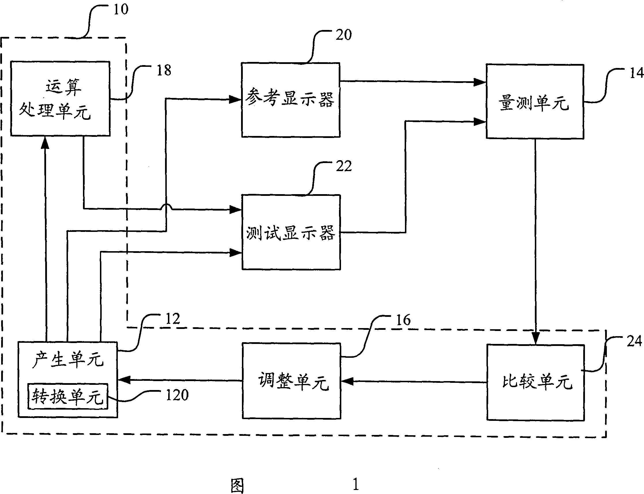
[0034] Please refer to FIG. 1 , which is a block diagram of a preferred embodiment of the present invention. As shown in the figure, the image calibration system of the display device of the present invention includes a generation unit 12 , a measurement unit 14 , an adjustment unit 16 and an operation processing unit 18 . The generation unit 12 is used to generate a reference color data and a test color data, and send them to a reference display 20 and a test display 22 respectively, and display a reference color and a test color, wherein the generation unit 20 can be in red and green In the blue color coordinate format (RGBcolor space), multiple color data are sampled as reference color data. In this embodiment, RrGrBr represents the...


PUM


Abstract

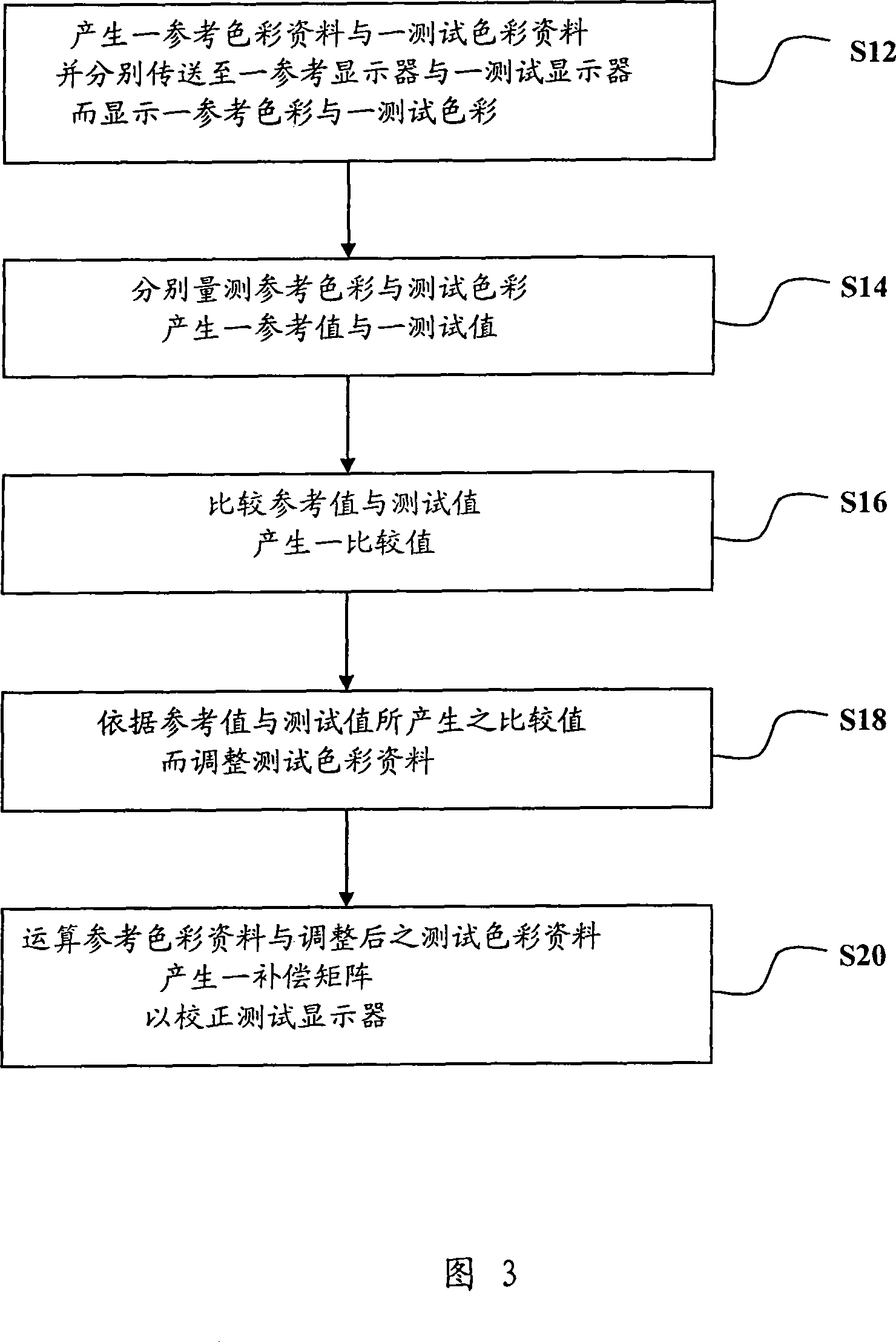
The present invention relates to an image correction system and correction method of a display device. A reference color data and a test color data are generated by a generating unit and sent to a reference display and a test display respectively to display a reference color and a test color. To test the color, the measurement unit measures the reference color and the test color respectively to generate a reference value and a test value, the adjustment unit adjusts the test color data according to the reference value and the test value, and the operation processing unit receives the reference color data and the adjusted color Test the color data, and calculate the reference color data and the adjusted test color data to generate a compensation function to calibrate the test display.

Description

Technical field: [0001] The present invention relates to a calibration system and calibration method, in particular to an image calibration system and calibration method of a display device. Background technique: [0002] According to the vigorous development of science and technology nowadays, the types of information products are introduced to meet the different needs of many people. Most of the early monitors were cathode ray tube (CRT) monitors. Due to their bulky size and high power consumption, and the radiation generated, they may be harmful to the health of users who use the monitor for a long time. Therefore, Displays on the market today will gradually be replaced by liquid crystal displays (Liquid Crystal Displays, LCDs) for old CRT displays. Liquid crystal displays have the advantages of being thin, light and small, low radiation and low power consumption, and thus become the mainstream in the current market. [0003] Generally, when the display leaves the facto...

Claims


Application Information

Patent Timeline
IPC IPC(8): G09G3/36G09G3/20G09G5/02G09G5/06G09G5/10G02F1/133G01J3/46
Inventor 黄昭世陈信宇苏镇港
Owner ACER INC
Learn More