
A method and system for gain calibration of digital receiver channel

A technology of digital receiver and channel gain, applied in transmitter/receiver shaping network, baseband system components, etc., can solve the adverse effects of sampling circuit thermal noise and receiver noise figure, and cannot support multiple receivers Simultaneous calibration, not suitable for large-scale production and other problems, achieve the effect of reducing calibration time and equipment cost, fast and accurate gain adjustment, and eliminating the influence of thermal noise and receiver noise figure

Inactive Publication Date: 2010-06-30
ST ERICSSON SEMICON BEIJING
View PDF4 Cites 0 Cited by
  • Summary
  • Abstract
  • Description
  • Claims
  • Application Information

AI Technical Summary

Problems solved by technology

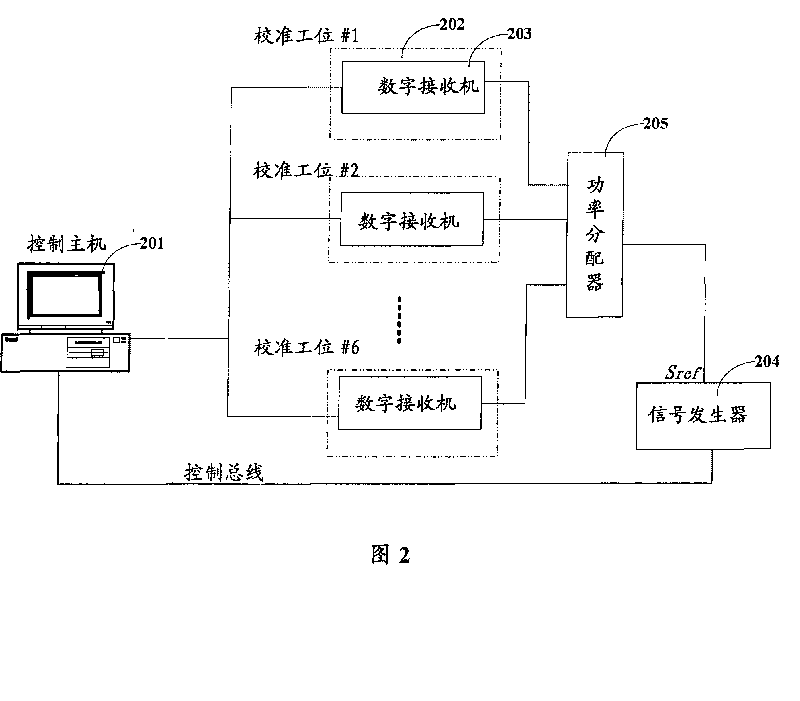
[0004] The purpose of the present invention is to provide a method and system for calibrating digital receiver channel gain, which solves the problem of low calibration efficiency caused by simultaneous calibration of multiple receivers in the existing digital receiver calibration system and is not suitable for large-scale production, and the sampling circuitry of existing calibration systems suffers from thermal noise and receiver noise figure disadvantages at higher channel gains

Method used


Image

  • A method and system for gain calibration of digital receiver channel
  • A method and system for gain calibration of digital receiver channel
  • A method and system for gain calibration of digital receiver channel

Examples


Embodiment Construction

[0024] In order to make the purpose, technical features and implementation effects of the present invention clearer, the technical solution of the present invention will be described in detail below in conjunction with the accompanying drawings and specific embodiments.

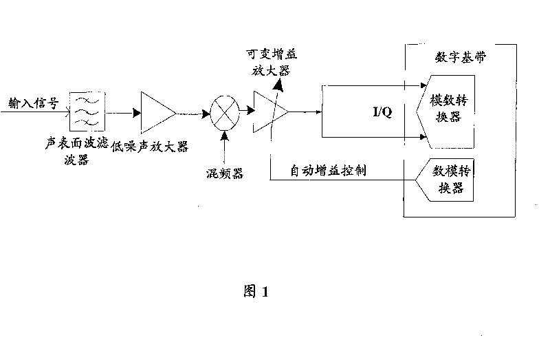
[0025] The object of the present invention is to provide a kind of method and system to digital receiver channel gain calibration, with figure 1The common digital receiver described is taken as an example, and the channels of the digital receiver usually include components such as SAWF, LNA, mixer, and VGA. Due to the inconsistency of devices, the influence of production process deviation and other factors, different digital receivers may have different channel gains under the same VGA control voltage; in order to quickly and accurately adjust the analog input signal entering the sampling circuit to the normal amplitude , also in order to ensure that the measurement accuracy of the system can meet the require...


PUM


Abstract

The invention provides a method and a system for digital receiver channel gain calibration. The method comprises that step one, a calibrating digital receiver sets up a communication connection with a control mainframe after the opening of the receiver; step two, the digital receiver and the received calibration signals carry out an initial synchronization, and the control mainframe and the digital receiver carry out an initial channel gain alignment after the completion of the initial synchronization; step three, the control mainframe forecasts a control word step size, and determines a corresponding channel gain of the control word step size; step four, the control mainframe establishes a channel gain calibration table according to the recorded control word step size and the channel gain. With the art, the invention supports a simultaneous calibration of a plurality of receivers, which decreases calibration time of receivers and suits for a mass production of receivers. And due to adynamic forecast for a channel gain control coefficient, the calibration speed is improved, the effect of thermal noise and noise coefficient of the receiver at a higher channel gain is eliminated, and the calibration precision is enhanced.

Description

technical field [0001] The invention relates to a technique for calibrating a receiver, in particular to a method and a system for calibrating the channel gain of a digital receiver. Background technique [0002] figure 1 It is a schematic diagram of the structure of a commonly used digital receiver. The input signal enters the receiver from the input port, passes through the surface acoustic wave filter (SAWF, Surface Acoustic Wave Filter) and then reaches the low noise amplifier (LNA, Low Noise Amplifier). After passing through the LNA, the input The signal and the local oscillator signal are multiplied in the mixer, and the baseband signal is output. The baseband signal is amplified by a variable gain amplifier (VGA, VariableGain Amplifier) ​​and then sent to the sampling circuit. The digital signal obtained after sampling enters the digital baseband. Subsequent digital signal processing. Since the amplitude of the input signal will change with the application, transmis...

Claims


Application Information

Patent Timeline
Patent Type & Authority Patents(China)
IPC IPC(8): H04L25/02H04L25/03
Inventor 冯星辉杨龙波
Owner ST ERICSSON SEMICON BEIJING
Learn More