Cai's circuit inductor current oscilloscope display circuit

A technology of Chua's circuit and display circuit, which is applied in cathode ray oscilloscope, digital variable/waveform display, instrument, etc., and can solve the problem that the phase diagram cannot be displayed

Inactive Publication Date: 2008-02-20
张新国
View PDF0 Cites 2 Cited by
  • Summary
  • Abstract
  • Description
  • Claims
  • Application Information

AI Technical Summary

Problems solved by technology

There are 3 changing physical quantities in Chua's circuit: voltage V C1 , voltage V C2 with current I L , voltage V C1 with voltage V C2 can be observed using an oscilloscope display, while the current I L cannot use an oscilloscope to display observations, so that the oscilloscope can only display two of the three waveforms in Chua's circuit
For the phase diagram, the three waveforms in Chua’s circuit can be combined into three phase diagrams in two groups, that is, V C1 -V C2 phase diagram, V C1 -I L phase diagram, I L -V C2 phase diagram, the oscilloscope can only display V C1 -V C2 phase diagram, and cannot display V C1 -I L with I L -V C2 Phase diagram, this is the defect of Chua's circuit oscilloscope display observation method

Method used


Image

  • Cai's circuit inductor current oscilloscope display circuit
  • Cai's circuit inductor current oscilloscope display circuit
  • Cai's circuit inductor current oscilloscope display circuit

Examples


Embodiment 1

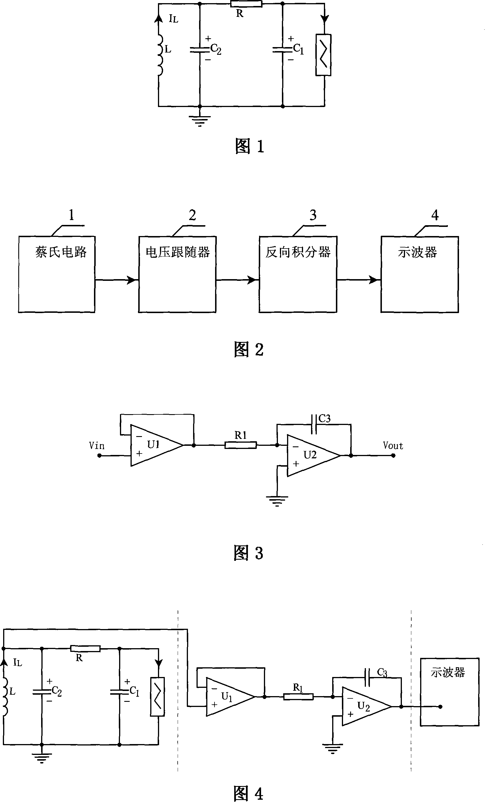
[0016] Embodiment 1 Referring to Fig. 3 and Fig. 4, the described current-voltage conversion circuit is composed of two operational amplifiers, a resistor and a capacitor, the first operational amplifier U 1 The non-inverting input terminal is connected to one arm of the inductor L of the tested Chua circuit, and the inverting input terminal is connected to the output terminal to form a voltage follower 1; the first operational amplifier U 1 The output terminal is connected to the resistor R 1 , resistor R 1 Connect the other end of the second operational amplifier U 2 inverting input, the second op amp U 2 The non-inverting input is connected to ground, and the second op amp U 2 A capacitor C is connected between the inverting input and the output 3 , resistor R 1 , capacitance C 3 with the second op amp U 2 constitutes the inverse integrator 3, the second operational amplifier U 2 The output end is connected with the signal measuring probe of the oscilloscope 4 .

...

Embodiment 2

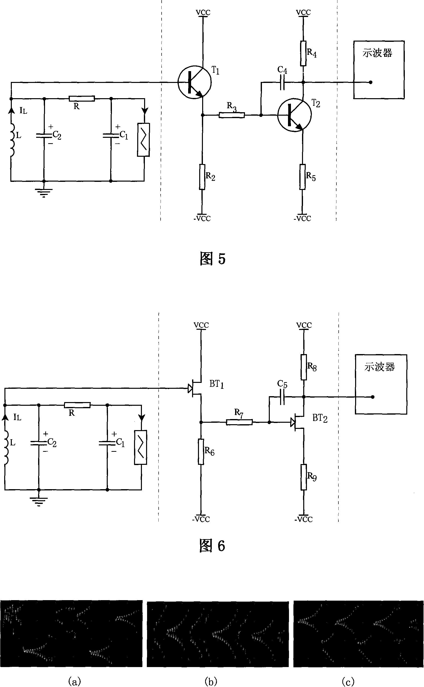
[0024] Embodiment 2 Referring to FIG. 5, the current-voltage conversion circuit is composed of two triodes, 4 resistors and a capacitor. The first triode T 1 The base is connected to one arm of the inductor L of the tested Chua's circuit, and the first transistor T 1 The collector is connected to the positive power supply, and the first triode T 1 emitter through a series resistor R 2 Connected to the negative power supply, the first triode T 1 , resistance R 2 Form a voltage follower 2; the first transistor T 1 Emitter connection resistance R 3 , resistor R 3 The other end is connected to the second transistor T 2 base, the second transistor T 2 A capacitor C is connected between the base and collector of 4 ;The second transistor T 2 collector through a series resistor R 4 Connect to the positive power supply, the second triode T 2 the emitter through a series resistor R 5 Connected to the negative power supply, the second triode T 2 , capacitance C 4 and resist...

Embodiment 3

[0026] Embodiment 3 Referring to Fig. 6, the described current-voltage conversion circuit is composed of two field effect transistors, 4 resistors and a capacitor, the first field effect transistor BT 1 The gate is connected to one arm of the inductor L of the tested Chua's circuit, the first field effect transistor BT 1 The drain is connected to the positive power supply, the first field effect transistor BT 1 the source through a series resistor R 6 Connect to the negative power supply, the first FET BT 1 , resistance R 6 Form a voltage follower 2; the first field effect transistor BT 1 Source connection resistance R 7 , resistor R 7 The other end of the connection to the second field effect transistor BT 2 Gate, the second FET BT 2 A capacitance C is connected between the gate and drain of 5 ;Second FET BT 2 The drain through the series resistor R 8 Connect to the positive power supply, the second FET BT 2 the source through a series resistor R 9Connected to the...


PUM


Abstract

The utility model discloses an oscilloscope display circuit for the inductor current in Chua's circuit, which is characterized in that: the voltage relating to the current IL of the inductor L in the Chua's circuit (1) is reflected on the arm of the inductor L and is transferred to a reverse integrator (3) via a voltage follower (2) of the conversion circuit; the output voltage variable is proportional to the inductor current, thus the current-to-voltage conversion is realized and displayed on an oscilloscope (4). The utility model can directly measure and display the current flow of the Chua's circuit by an oscilloscope; the numbers of the three Chua's circuit waveforms which can be measured and displayed by the oscilloscope is enlarged from two to three, and the numbers of the three Chua's circuit phase diagrams also is enlarged to three compared with the original number two; thereby the oscilloscope is suitable for the debugging of the Chua's circuit and is more suitable for the teaching of the college chaos experiment and the demonstration of the science popularization chaos experiment in Chua's circuit.

Description

technical field [0001] The invention belongs to nonlinear circuit, commonly called chaotic circuit, and relates to an oscilloscope display circuit for inductor current of Chua's circuit. Background technique [0002] Chua's circuit is a chaotic circuit, which is a third-order autonomous circuit composed of linear resistance, capacitance, inductance and nonlinear "Chua's diode", which meets the conditions for generating chaos. As shown in Figure 1. There are 3 changing physical quantities in Chua's circuit: voltage V C1 , voltage V C2 with current I L , voltage V C1 with voltage V C2 can be observed using an oscilloscope display, while the current I L Observations cannot be displayed using an oscilloscope, so the oscilloscope can only display two of the three waveforms in Chua's circuit. For the phase diagram, the three waveforms in Chua’s circuit can be combined into three phase diagrams in two groups, that is, V C1 -V C2 phase diagram, V C1 -I L phase diagram, I ...

Claims


Application Information

Patent Timeline
Patent Type & Authority Applications(China)
IPC IPC(8): G01R13/00G01R13/22
Inventor 张新国陈昱莅朱雪丰
Owner 张新国
Why Eureka
Try Eureka