
Power supplier for field emission display

A technology of power supply and display, applied in static indicators, instruments, electrical components, etc., can solve problems such as large electromagnetic interference, unfavorable system anti-electromagnetic interference, and increase cost, so as to reduce electromagnetic interference effects and reduce electromagnetic interference sources. , is conducive to the effect of miniaturization

Inactive Publication Date: 2008-02-20
HOLTEK SEMICON
View PDF0 Cites 16 Cited by
  • Summary
  • Abstract
  • Description
  • Claims
  • Application Information

AI Technical Summary

Problems solved by technology

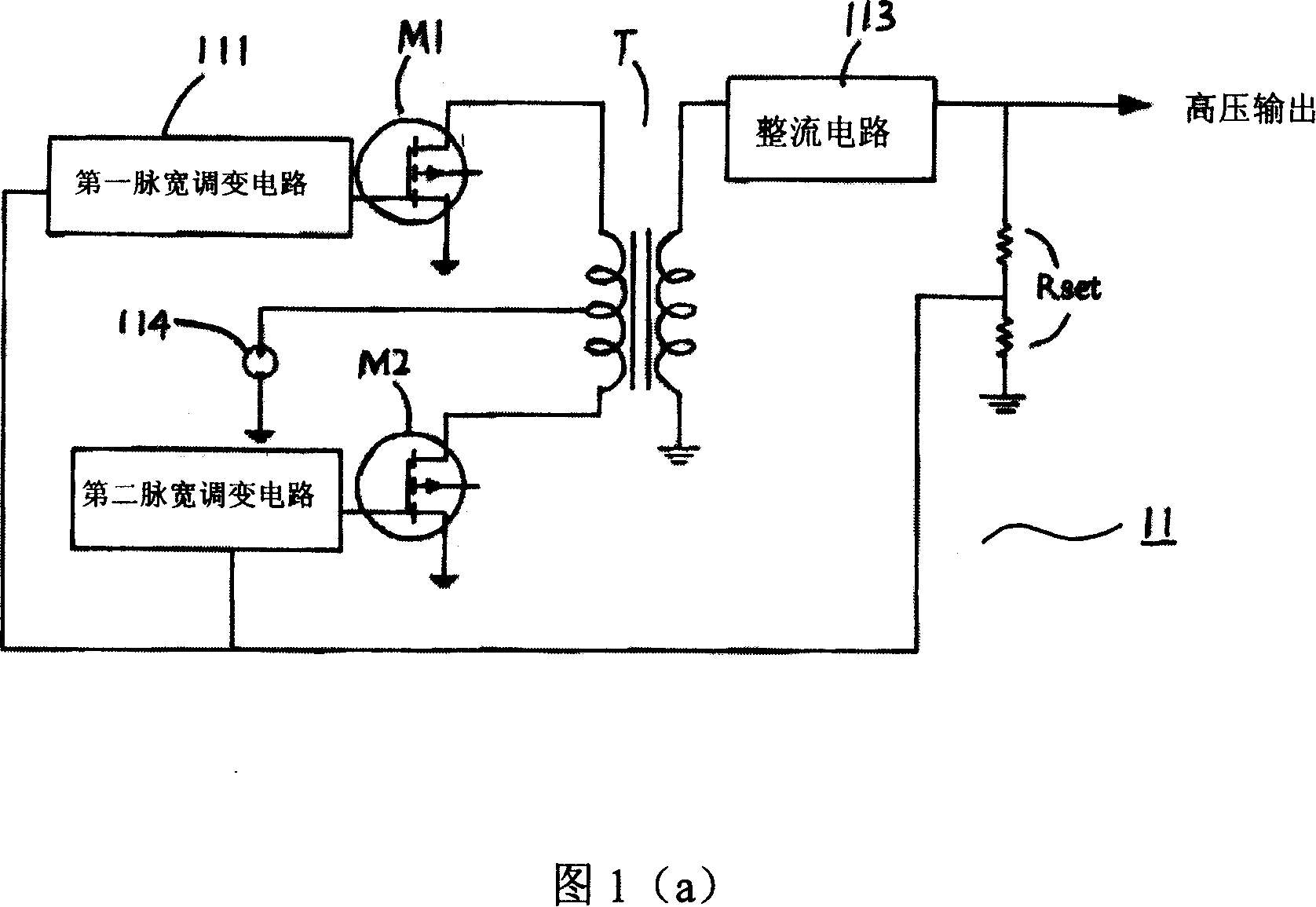
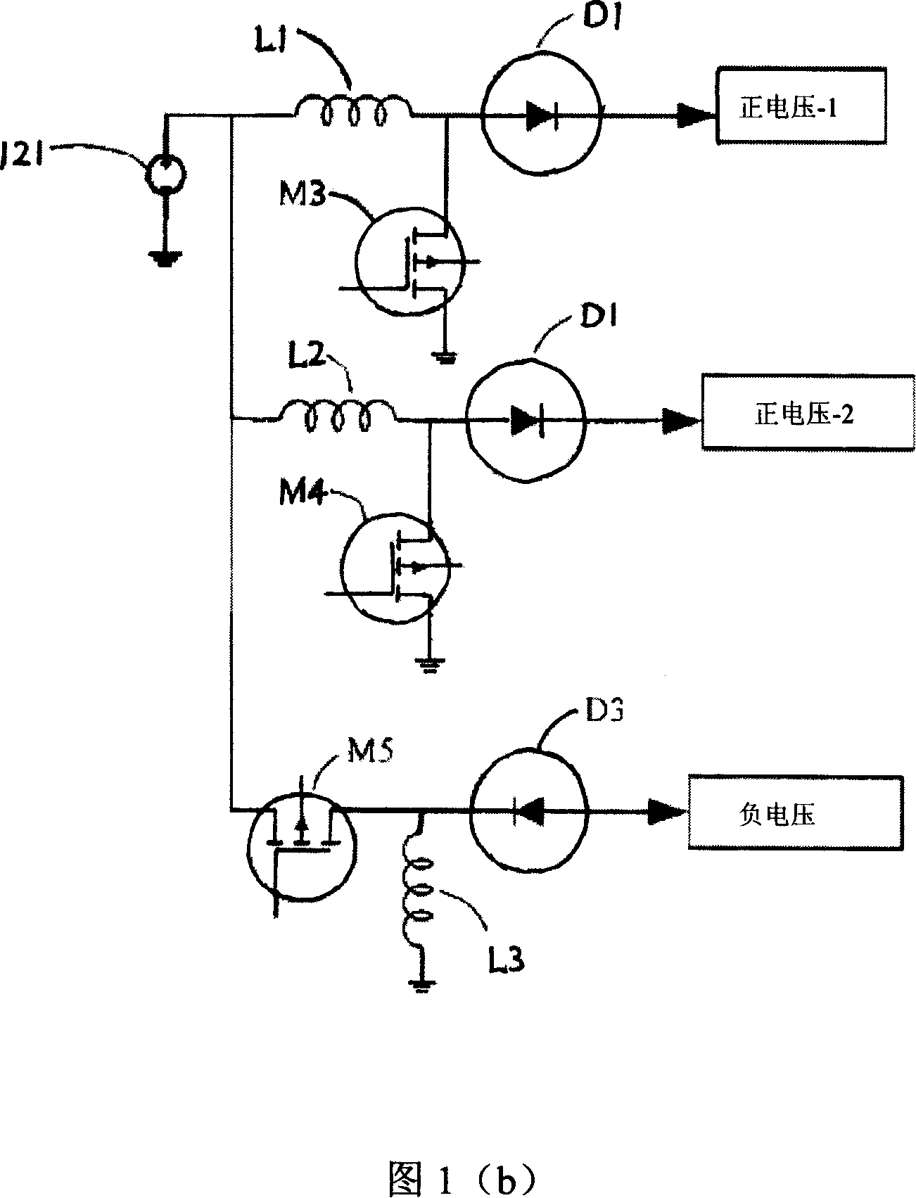
However, these four sets of conversion circuits not only take up a lot of space and are not conducive to the miniaturization of the power supply, but also the existence of magnetic components such as three inductors L1-L3 and the transformer T will generate greater electromagnetic interference.
Therefore, the conventional circuit structure of the power supply used in the field emission display will not only increase the cost, but also be detrimental to the performance of the system against electromagnetic interference

Method used


Image

  • Power supplier for field emission display
  • Power supplier for field emission display
  • Power supplier for field emission display

Examples


Embodiment Construction

[0064] Please refer to FIG. 2 , which is a circuit block diagram of a power supply for a field emission display proposed by the present invention, wherein the power supply 20 is composed of a high voltage output circuit 30 and a medium high voltage / low voltage / negative voltage output circuit 40 .

[0065] The high voltage output circuit 30 is composed of a flyback converter 301 and a voltage doubler rectifier circuit 302 for outputting a high voltage.

[0066]The middle and high voltage / low voltage / negative voltage output circuit 40 is composed of a booster circuit 401, a first charge pump circuit 404, a linear voltage regulator circuit 405, a second charge pump circuit 406, and a negative voltage regulator circuit 407 to output A medium-high voltage, a negative voltage, and a low voltage. Wherein, the operation of the booster circuit 401 can output the low voltage, the booster circuit 401, the first charge pump circuit 404 and the linear voltage regulator circuit 405 work tog...


PUM


Abstract

The utility model relates to a power supply used for the field emission display, comprising a power source controller, a high voltage output circuit and a high voltage / low voltage / negative voltage output circuit; wherein the power source controller comprises a pulse frequency modulator, an oscillator, a comparator and a digital logic circuit, which are used to drive the external system circuit; the high voltage output circuit comprises a flyback converter and a voltage doubling rectifier circuit, which are used for outputting a high voltage; the high voltage / low voltage / negative voltage output circuit comprises a booster circuit which is used for outputting a low voltage, a voltage tripler charge pump and a linear voltage-stabilizing circuit which are used for outputting a middle high voltage, a two times voltage charge pump circuit and a negative voltage-stabilizing circuit which are used for outputting a negative voltage.

Description

technical field [0001] The invention relates to a power supply, in particular to a power supply applied to a field emission display. Background technique [0002] The so-called field emission display (Field Emission Display, FED), its principle is very similar to the cathode ray tube (Cathode Ray Tube, CRT). A display technology. The cathode ray tube uses a single thermal electron gun or three thermal electron guns to emit electrons, and then bends the electrons through the electromagnetic field to make them hit the required corresponding phosphor position; therefore, when the size of the cathode ray tube display increases, the electron beam The path required for deflection to occur must also be increased, which increases its thickness. The field emission display has its own electron emission source under each pixel, so that the electrons will not need to be deflected and can directly hit the phosphor to emit light, realizing the concept of thinning the cathode ray tube di...

Claims


Application Information

Patent Timeline
Patent Type & Authority Applications(China)
IPC IPC(8): H02M3/28H02M7/48H02M7/537H02M7/10H02M3/07G09G3/00
Inventor 叶鸿腾
Owner HOLTEK SEMICON
Learn More