Battery pack

A technology for battery packs and battery modules, which is applied to battery pack components, secondary batteries, battery caps/end caps, etc., can solve the problem of not improving the work efficiency of assembled battery packs, and achieves a reduction in the number and an increase in the number of battery packs. Efficiency, material cost effect

Inactive Publication Date: 2008-02-20
TOYOTA JIDOSHA KK
View PDF1 Cites 27 Cited by
  • Summary
  • Abstract
  • Description
  • Claims
  • Application Information

AI Technical Summary

Problems solved by technology

It employs a fixing structure in which different bolts are used for mounting the upper case to the lower case and the battery pack itself to the vehicle, thereby not improving the work of assembling the battery pack and fixing it to the vehicle efficiency

Method used


Image

  • Battery pack
  • Battery pack
  • Battery pack

Examples


no. 1 example

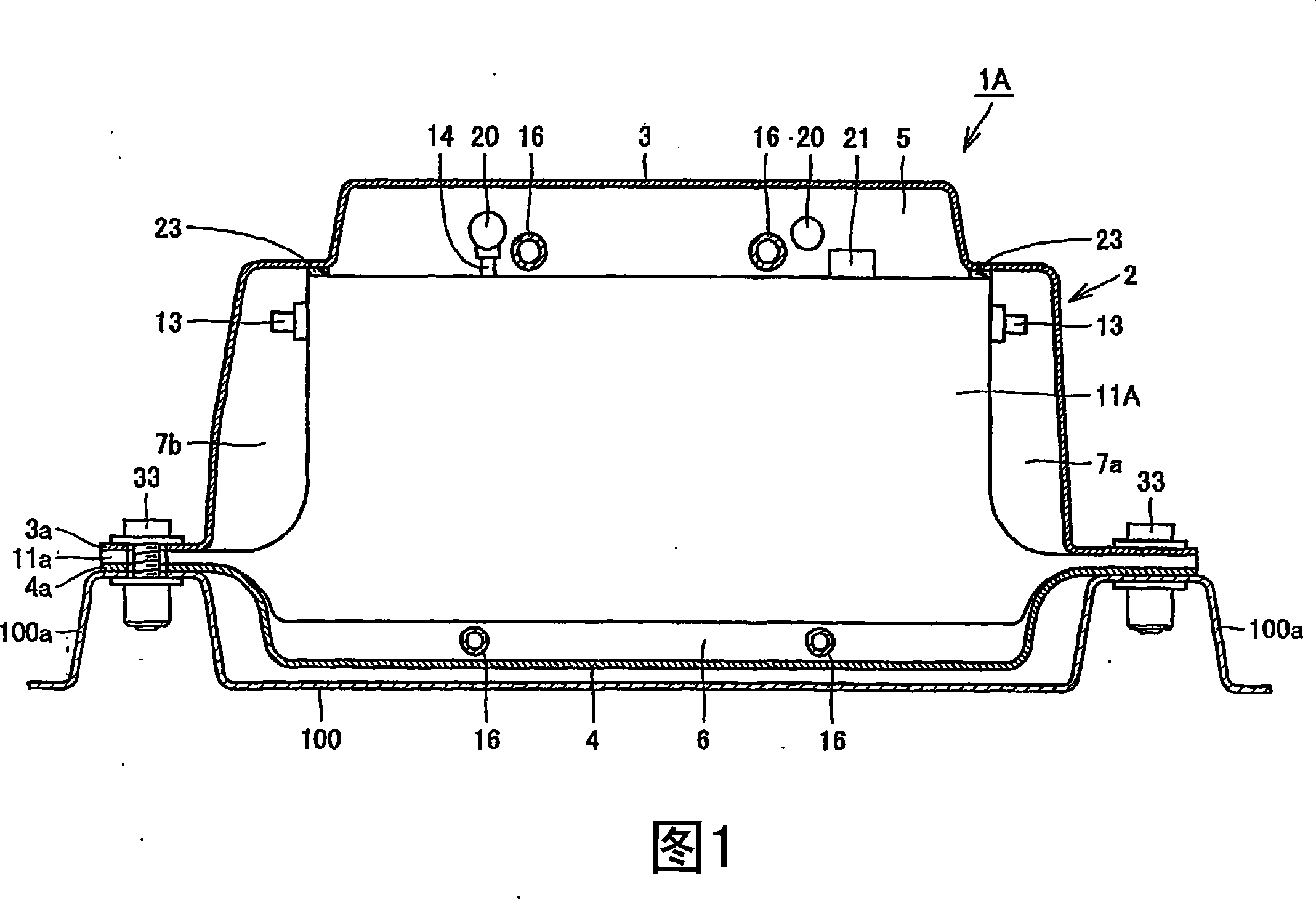
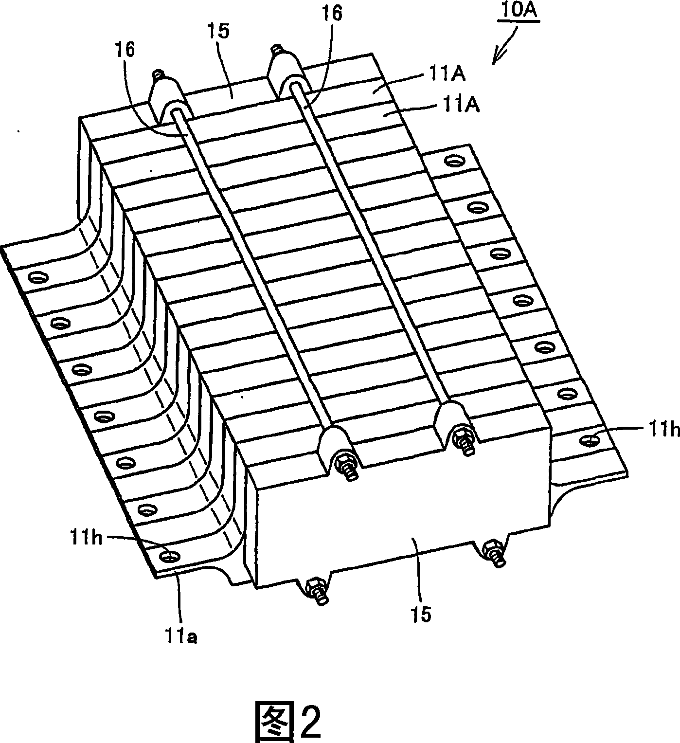
[0025] First, referring to FIGS. 1 and 2 , the battery pack of the present embodiment will be described. FIG. 1 is a schematic cross-sectional view of the battery pack 1A in a direction perpendicular to the stacking direction of the battery modules 11A. FIG. 2 is an overall perspective view showing the structure of the battery pack 10A of the first embodiment of the present invention. Although the battery module 11A shown in this embodiment is a nickel-cadmium battery type, other batteries such as nickel-metal hydride batteries may also be used.

[0026] The battery pack 1A of the present embodiment is a battery pack in which a battery assembly 10A in which a plurality of battery modules 11A are stacked is stored in a battery case 2 . The battery case 2 has an upper case 3 and a lower case 4 . The upper case 3 is provided with an upper case flange portion 3 a protruding laterally and extending in the stacking direction of the battery modules 11A (direction perpendicular to t...

no. 2 example

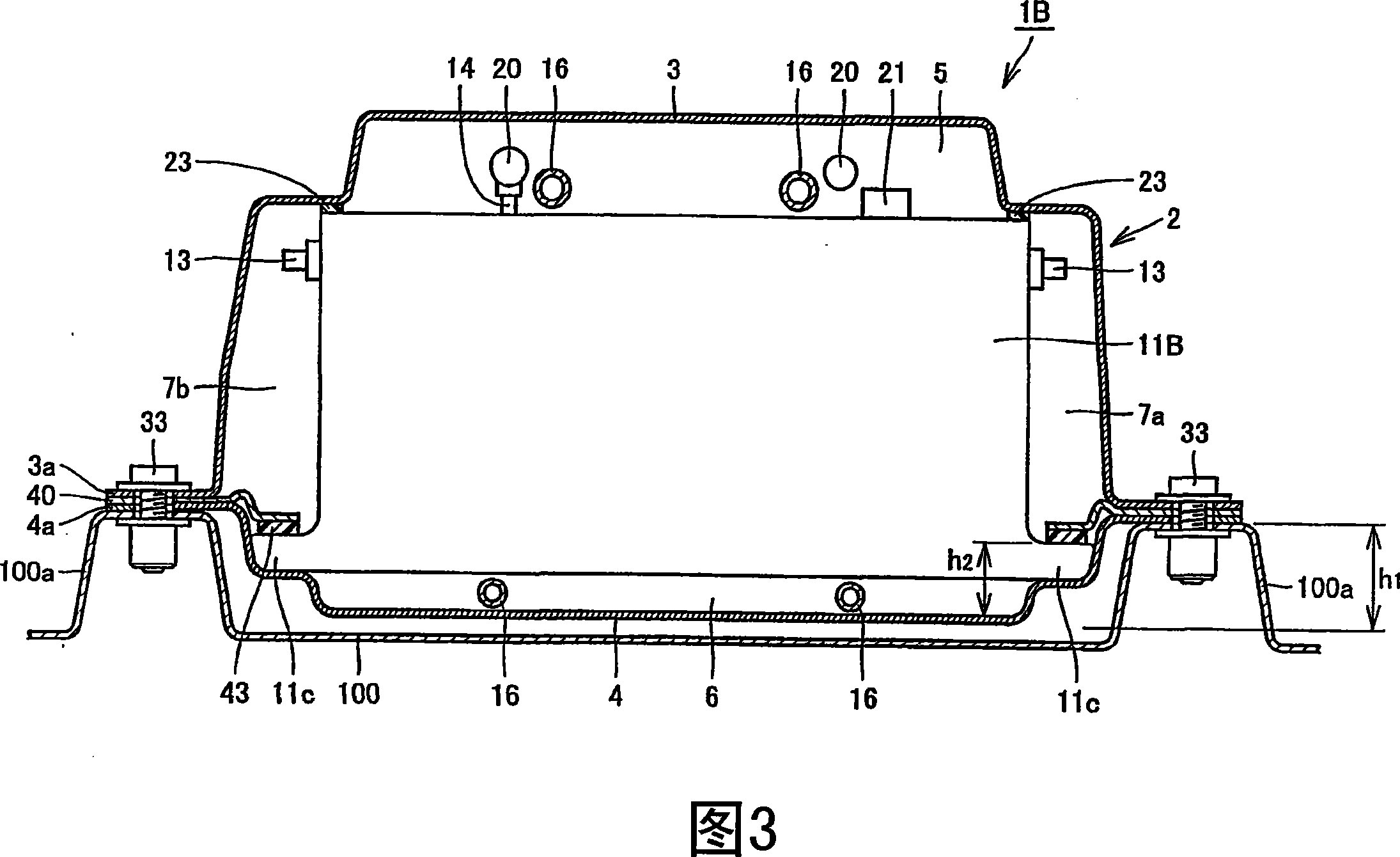
[0033] Next, referring to FIGS. 3 and 4 , the battery pack of the present embodiment and the fixing structure of the battery pack will be described. 3 is a schematic sectional view of the battery pack 1B in a direction perpendicular to the stacking direction of the battery pack 1B. FIG. 4 is an overall perspective view showing the structure of the battery pack 10B of this embodiment. The battery module 11B of this embodiment is a nickel-cadmium battery type.

[0034] Comparing the battery pack 1B of this embodiment with the battery pack 1A of the first embodiment, the difference lies in the fixing structure of the battery module 11B to the battery box 2 . Specifically, similar to the first embodiment, according to the battery pack 1B of the present embodiment, the upper case 3 and the lower case 4 are provided with an upper case flange portion 3 a and a lower case extending in the stacking direction of the battery modules 11B. Case flange portion 4a. The battery pack 10B is...

no. 3 example

[0041] Hereinafter, the battery pack 1C of the present embodiment will be described with reference to FIGS. 5 and 6 . FIG. 5 is an overall perspective view showing the structures of the battery pack 1C and the battery pack 50A of the present embodiment. FIG. 6 is a partially exploded perspective view showing the detailed structure of the battery pack 50A. The battery module 54A (described below) of this embodiment is a lithium-ion battery type.

[0042] The battery pack 1C of the present embodiment is a battery pack in which the battery pack 50A is stored inside the battery case 2 . Similar to the above-described embodiments, the battery case 2 has an upper case 3 and a lower case 4 . The upper case 3 is provided with an upper case flange portion 3 a projecting laterally and extending in a stacking direction of battery modules 54A (described below) constituting the battery assembly 50A. Similarly, the lower case 4 is provided with a lower case flange portion 4 a projecting ...


PUM


Abstract

In a battery pack, battery pack flange portions (11a) are provided at opposing sides of a battery assembly (10A) along a stacking direction of battery modules (11A), so as to project laterally. The battery module flange portions (11a) are interposed between an upper case flange portion (3 a) and a lower case flange portion (4a) when the upper case flange portion (3 a) and the lower case flange portion (4a) are overlaid, and fastened and fixed concurrently by bolts (33). The bolts (33) are also used in fixing the battery pack (1A) to a vehicle (100). With this configuration, a battery pack that can reduce assembly steps with the bolts and the like to improve efficiency in the fastening work can be provided.

Description

technical field [0001] The present invention relates to the structure of a battery pack incorporated in a vehicle such as an electric vehicle. Background technique [0002] In recent years, electric vehicles employing a motor as a drive source or so-called hybrid vehicles in which a motor as a drive source and other drive sources are combined have been put into practical use. The vehicle described above includes a battery for supplying electric power as energy to the motor. For example, a secondary battery (represented by a nickel-cadmium battery, a nickel-metal hydride battery, a lithium-ion battery, etc.) that can be repeatedly charged and discharged can be used as the above-mentioned battery. [0003] A secondary battery is composed of a battery module in which battery cells are stacked. The battery module is stored in the battery box, and is incorporated in the vehicle in this state. The above-mentioned battery box, battery module and other internal components stored ...

Claims


Application Information

Patent Timeline
Patent Type & Authority Applications(China)
IPC IPC(8): H01M2/10B60L11/18H01M50/211H01M50/249H01M50/262H01M50/271H01M50/528
CPCY02E60/12H01M2/1072H01M10/5059H01M10/5004H01M10/0525Y02T10/7005H01M10/5016H01M10/5032B60L11/1874H01M10/5067Y02T10/7011H01M2/1077H01M2/22Y02T10/705B60L11/1879H01M2/1083H01M2/1016H01M10/625H01M10/6563H01M10/647H01M10/6557H01M10/613B60L58/26B60L50/64Y02E60/10Y02T10/70H01M50/528H01M50/249H01M50/211H01M50/262H01M50/271
Inventor 渡边功小柳起
Owner TOYOTA JIDOSHA KK
Why Eureka
Try Eureka