
Adjustable metal composite type low-yield point damper

A low-yield point, composite technology, applied in building components, shockproof, etc., can solve the problems of high maintenance cost, unfavorable on-site installation and debugging, and shock absorption effect lower than the design value, etc., to achieve low material cost and reduced yield strength. , the effect of easy installation

Inactive Publication Date: 2008-02-27
BEIJING UNIV OF TECH
View PDF0 Cites 28 Cited by
  • Summary
  • Abstract
  • Description
  • Claims
  • Application Information

AI Technical Summary

Problems solved by technology

Most of the existing dampers belong to the package structure, which is not conducive to on-site installation and debugging, and the maintenance cost is high; at the same time, due to the damper with high yield strength, the characteristics of hysteretic energy consumption of the material cannot be fully utilized under medium and small earthquakes. The shock absorption effect is often lower than the design value

Method used


Image

  • Adjustable metal composite type low-yield point damper
  • Adjustable metal composite type low-yield point damper
  • Adjustable metal composite type low-yield point damper

Examples


Embodiment 1

[0028] Specific embodiments of the present invention will be described in detail below in conjunction with the accompanying drawings.

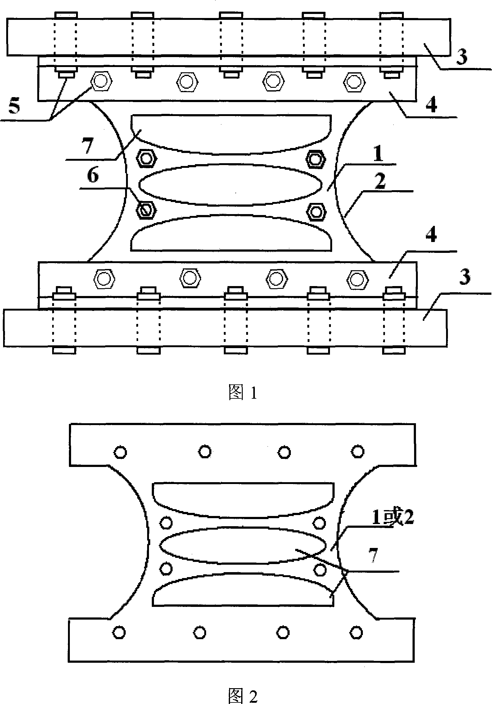
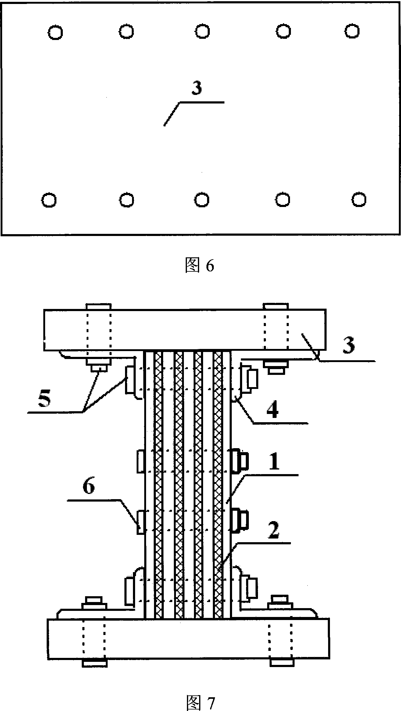
[0029] This embodiment mainly includes five first energy-dissipating metal plates 1 with higher yield points, four second energy-dissipating metal plates 2 with lower yield points, angle steel plates 4 and upper and lower horizontal connecting steel plates 3 . The upper and lower horizontal connecting steel plates 3 are connected with the building structure through large high-strength bolts 5 . Five first energy-dissipating metal plates 1 and four second energy-dissipating metal plates 2 are arranged alternately, as shown in Figure 7 and Figure 8, the shapes of the first energy-dissipating metal plates 1 and the second energy-dissipating metal plates 2 are exactly the same, The first energy-dissipating metal plate 1 is a low-carbon steel plate, the second energy-dissipating metal plate 2 is a zinc plate, and the ratio of the total thickness of...

Embodiment 2

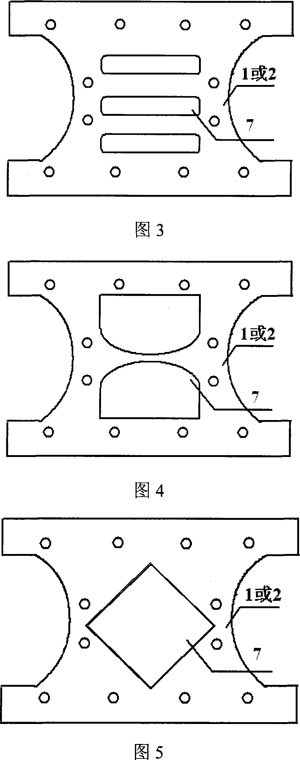
[0033] The structure of this embodiment is exactly the same as that of Embodiment 1, except that the first energy-dissipating metal plate 1 is a low-carbon steel plate, the second energy-dissipating metal plate 2 is a lead plate, and the total thickness of the low-carbon steel plate is the same as The total thickness ratio of the lead plate is 0.4:0.6. The hollow shapes of the first energy-dissipating metal plate 1 and the second energy-dissipating metal plate 2 are parallel rounded rectangles, as shown in FIG. 3 .

Embodiment 3

[0035] The structure of this embodiment is exactly the same as that of Embodiment 1, except that the first energy-dissipating metal plate 1 is an aluminum alloy plate, the second energy-dissipating metal plate 2 is a zinc plate, and the total thickness of the aluminum alloy plate is the same as that of the zinc plate. The total thickness ratio is 0.4:0.6. The hollow shapes of the first energy-dissipating metal plate 1 and the second energy-dissipating metal plate 2 are rhombus, as shown in FIG. 5 .


PUM

PropertyMeasurementUnit
Yield strengthaaaaaaaaaa

Abstract

The present invention relates to one kind of adjustable low yield point composite metal damper, and belongs to the field of shock resisting structural engineering technology and wind resisting technology. The adjustable low yield point composite metal damper consists of one first energy dissipating metal plate of material with yield strength greater than 200 MPa, one second energy dissipating metal plate of material with yield strength lower than 200 MPa, two horizontal connecting steel plates fixed to building structure, angle steel, high strength screws and one hollowed part. The first energy dissipating metal plate and the second energy dissipating metal plate are staggered and fixed between the horizontal connecting steel plates. The present invention is suitable for use in the crossed support point and the joint between beam and wall or column. The present invention has high energy dissipating capacity and other advantages.

Description

technical field [0001] The invention relates to an adjustable metal composite low-yield point damper, which belongs to the technical field of anti-seismic, shock-absorbing and wind-resistant structural engineering. Background technique [0002] Building structures under the action of strong earthquakes and strong winds should have sufficient energy dissipation capacity to avoid damage. Traditional earthquake-resistant and wind-resistant structural systems consume energy through the damage of structures and load-bearing components, resulting in varying degrees of damage or even collapse of structural components, which is unreasonable and unsafe. Structural energy dissipation and shock absorption technology is a new earthquake-resistant and disaster-prevention technology. In the structural system using energy dissipation and shock absorption technology, some non-load-bearing members of the structure are designed as special elements with greater energy dissipation capacity - da...

Claims


Application Information

Patent Timeline
IPC IPC(8): E04B1/98
Inventor 何浩祥闫维明纪金豹苏亮
Owner BEIJING UNIV OF TECH
Learn More