
Heat insulating method for reduction tank slag hole and reduction tank prepared by the method

A reduction tank and slag outlet technology, applied in the field of heat insulation, can solve problems such as large heat loss, and achieve the effects of preventing scalding accidents, reducing temperature, and reducing production costs

Inactive Publication Date: 2010-11-03
GUIZHOU SHIJI TIANYUAN MINING IND
View PDF4 Cites 0 Cited by
  • Summary
  • Abstract
  • Description
  • Claims
  • Application Information

AI Technical Summary

Problems solved by technology

It can effectively reduce the temperature of the slag outlet, solve the problem of large heat loss in the prior art, improve the working conditions of workers, prevent scald accidents, improve production efficiency, and reduce production costs

Method used


Image

  • Heat insulating method for reduction tank slag hole and reduction tank prepared by the method
  • Heat insulating method for reduction tank slag hole and reduction tank prepared by the method
  • Heat insulating method for reduction tank slag hole and reduction tank prepared by the method

Examples


Embodiment

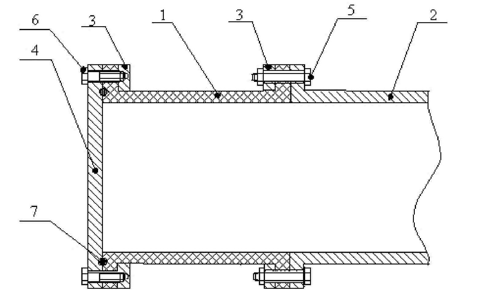
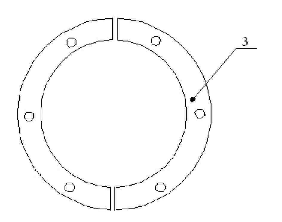
[0014] Embodiment: a heat insulation method for the slag outlet of a reduction tank, such as figure 1 , 2 , 3, the heat insulation section 1 made of non-metallic material is set at the slag outlet of the reduction tank, and the heat insulation section 1 is made of ceramic fiber non-metallic material with heat insulation effect, which blocks the kiln body with very high temperature. The transfer of heat from the reduction tank to the kiln body reduces the heat loss at the slag outlet, greatly reduces the temperature at the end cover of the slag outlet that needs to be disassembled frequently, and makes the sealing of the slag outlet easier to achieve, and The sealing is more reliable, and at the same time, workers do not need to open the end cover of the slag outlet to clean and restore waste slag at a very high temperature, which improves the working conditions of the workers and prevents scalding accidents.

[0015] The reduction tank prepared according to the heat insulatio...


PUM


Abstract

The present invention discloses one kind of reduction pot and its heat insulating method in the slag outlet. The reduction pot includes one pot body, one crystallizer on one end of the pot body, one heat insulating section made of non-metal material and connected through flanges to the other end of the pot body, and one slag outlet connected through flanges to the heat insulating section. The reduction pot has lowered slag outlet temperature, less heat loss, improved work condition, high safety, high production efficiency and low production cost.

Description

technical field [0001] The invention relates to a heat insulation method, in particular to a heat insulation method of a reduction tank and a reduction tank prepared by the method. Background technique [0002] The structure of the vacuum metal smelting reduction furnace is composed of a reduction tank, a crystallizer and a reduction furnace kiln body. The current reduction tank is placed horizontally in the kiln body, and the crystallizer is outside the kiln. Closed, supported on the tank body by the construction structure of the kiln body. The disadvantages are: the amount of material fed into the reduction tank is too small, so that the metal output rate of the reduction tank is low; at the same time, the reduction tank placed horizontally is inconvenient for charging, the labor intensity of the workers is high, and the heat utilization rate in the furnace is not high. Because the other end of the reduction tank is closed, after the reduction reaction is completed, the s...

Claims


Application Information

Patent Timeline
Patent Type & Authority Patents(China)
IPC IPC(8): F27B19/04F27D3/15C22B5/16
Inventor 张继强黄贵明
Owner GUIZHOU SHIJI TIANYUAN MINING IND
Learn More