Stretching time-delay test machine

A testing machine and test piece technology, applied in the testing of machine/structural components, using stable tension/pressure to test the strength of materials, measuring devices, etc. Easy to carry, small size and light weight effect

Inactive Publication Date: 2008-03-05
刘淑娟
View PDF0 Cites 3 Cited by
  • Summary
  • Abstract
  • Description
  • Claims
  • Application Information

AI Technical Summary

Problems solved by technology

The testing machine of the integral beam is bulky and needs enough space for placement. It is heavy and heavy, and it is not easy to carry as a whole, and it is not conducive to transport to the oil well site for operation.

Method used


Image

  • Stretching time-delay test machine
  • Stretching time-delay test machine

Examples


Embodiment Construction

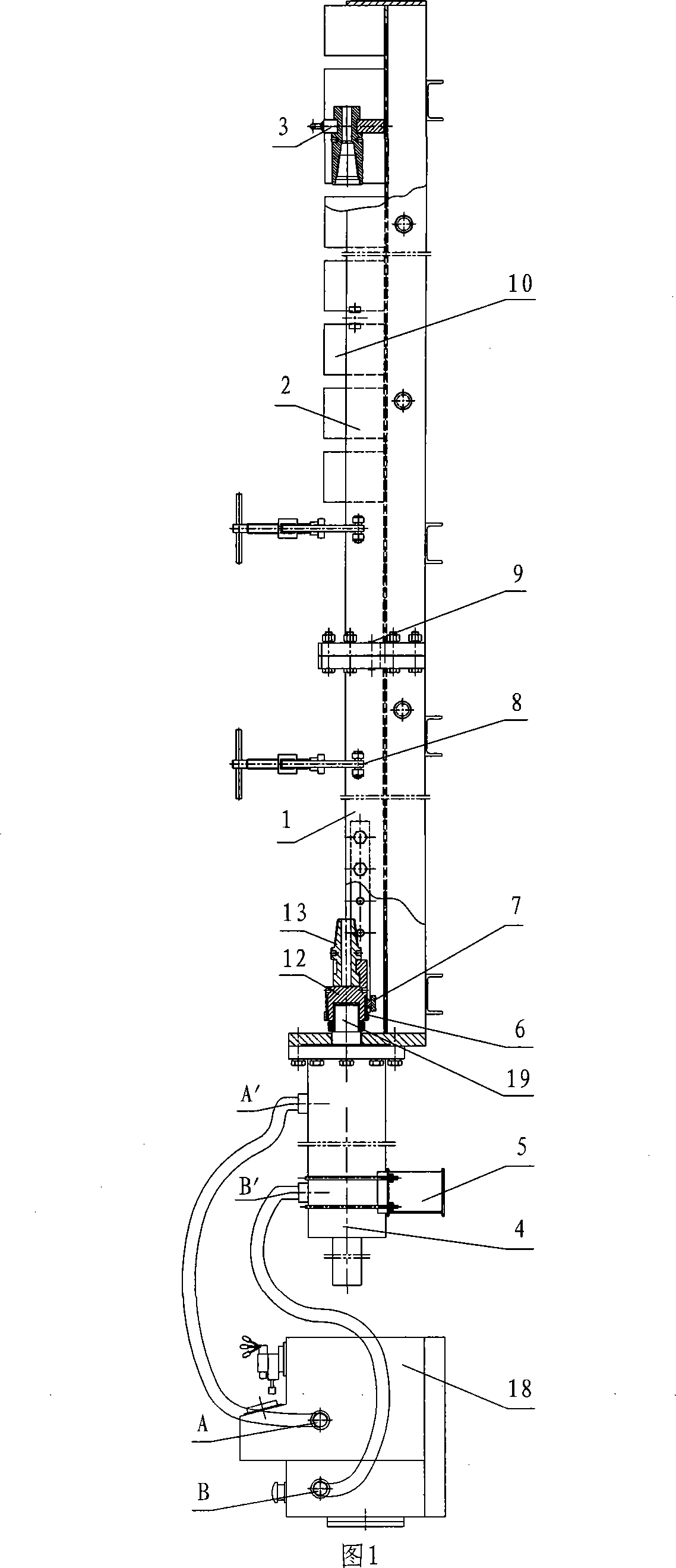
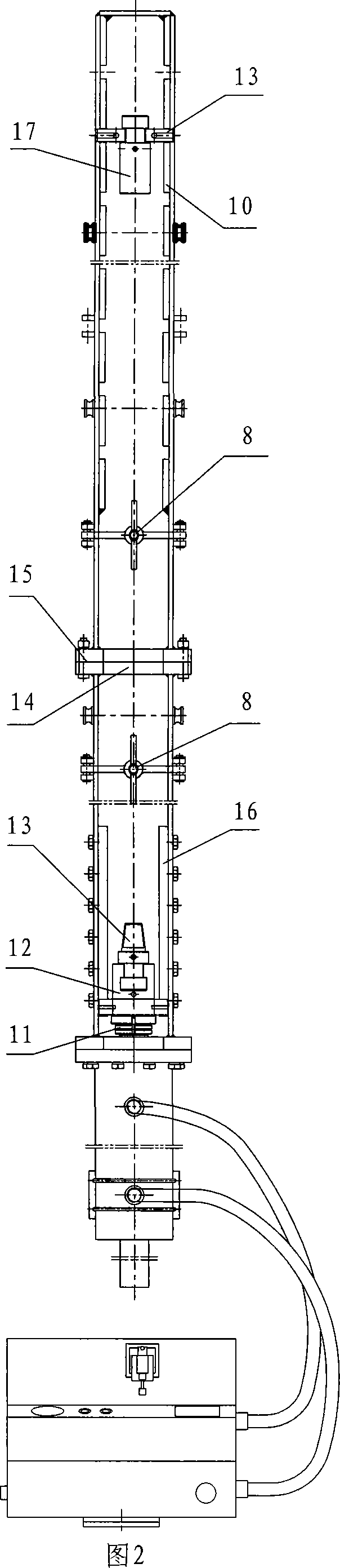
[0017] The present invention will be described in further detail below in conjunction with the accompanying drawings.

[0018] As shown in Fig. 1 and Fig. 2, the present invention is connected by the hydraulic cylinder 4 of front and rear beam assembly 1,2 and hydraulic mechanism and becomes rectangular structure. The front and rear beam assemblies 1 and 2 are connected by a single beam type, and one end of the front beam assembly 1 is detachably connected to the U-shaped connecting plate 14 on the rear beam assembly 2 through a U-shaped connecting plate 14 and a backing plate 15 through a bolt 9 connection, and the other end is detachably connected to the flange of the hydraulic cylinder 4 by bolts. Both sides of the front beam assembly 1 are provided with slide rails 16, which house a sliding seat assembly 7 that can reciprocate up and down. The sliding seat assembly 7 is extended with a ring sleeve to the main part of the front beam assembly, and the connecting nipple 12 i...


PUM


Abstract

The invention comprises a front beam assembly, a rear beam assembly, a control console and a hydraulic mechanism. The front and rear beam assemblies use single beam connection; the one end of front beam assembly is connected to the rear beam assembly in dismountable way; the other end of it is connected to the hydraulic cylinder in dismountable way; the hydraulic cylinder in the hydraulic mechanism is connected to the hydraulic fluid connection of the control console via pipeline; the tested component is mounted in the front beam assembly and rear beam assembly; the one end of the tested component connected to the front beam assembly can be stretched by hydraulic fluid cylinder. Said front beam assembly and rear beam assembly is a combined type mono-spar structure and can be dismounted according to the requirement.

Description

technical field [0001] The invention relates to a machine for temporarily testing on-site in an oil field, in particular to a tensile time-delay testing machine for an on-site downhole tool in an oil field. Background technique [0002] At present, many oil fields often need to perform tensile time-delay tests on downhole tools on site to test the performance of tools, such as testers, packers, jars and safety seals, etc. Time and shear pin shearing and other tests. Most of the existing tensile time-lapse testing machines use two beams as a whole, the specimen is placed between the two beams, and the hydraulic mechanism is controlled by the console to perform tensile testing on the specimen. The testing machine of the integral beam is bulky and needs enough space for placement, and is heavy in weight, making it inconvenient to carry as a whole, and it is not conducive to transportation to the oil well site for operation. Contents of the invention [0003] In order to sol...

Claims


Application Information

Patent Timeline
Patent Type & Authority Applications(China)
IPC IPC(8): G01N3/12G01M19/00G01M99/00
Inventor 刘淑娟许苏明
Owner 刘淑娟
Why Eureka
Try Eureka