Uninterrupted power supply and its configuration method

A technology of a power supply system and a configuration method, which is applied in the direction of circuit devices, emergency power supply arrangements, battery circuit devices, etc., can solve problems such as complex control, large footprint, and bulky volume, and achieve reduced volume and footprint, and easy transmission , the effect of simplifying the system

Inactive Publication Date: 2008-03-05
LIEBERT
View PDF0 Cites 15 Cited by
  • Summary
  • Abstract
  • Description
  • Claims
  • Application Information

AI Technical Summary

Problems solved by technology

The disadvantage of this structure is that it is bulky and occupies a large area. In addition, it needs to increase the control system of LBS and STS, which makes the control complicated.

Method used


Image

  • Uninterrupted power supply and its configuration method
  • Uninterrupted power supply and its configuration method

Examples


Embodiment Construction

[0014] The present invention will be further elaborated below according to the drawings and specific embodiments.

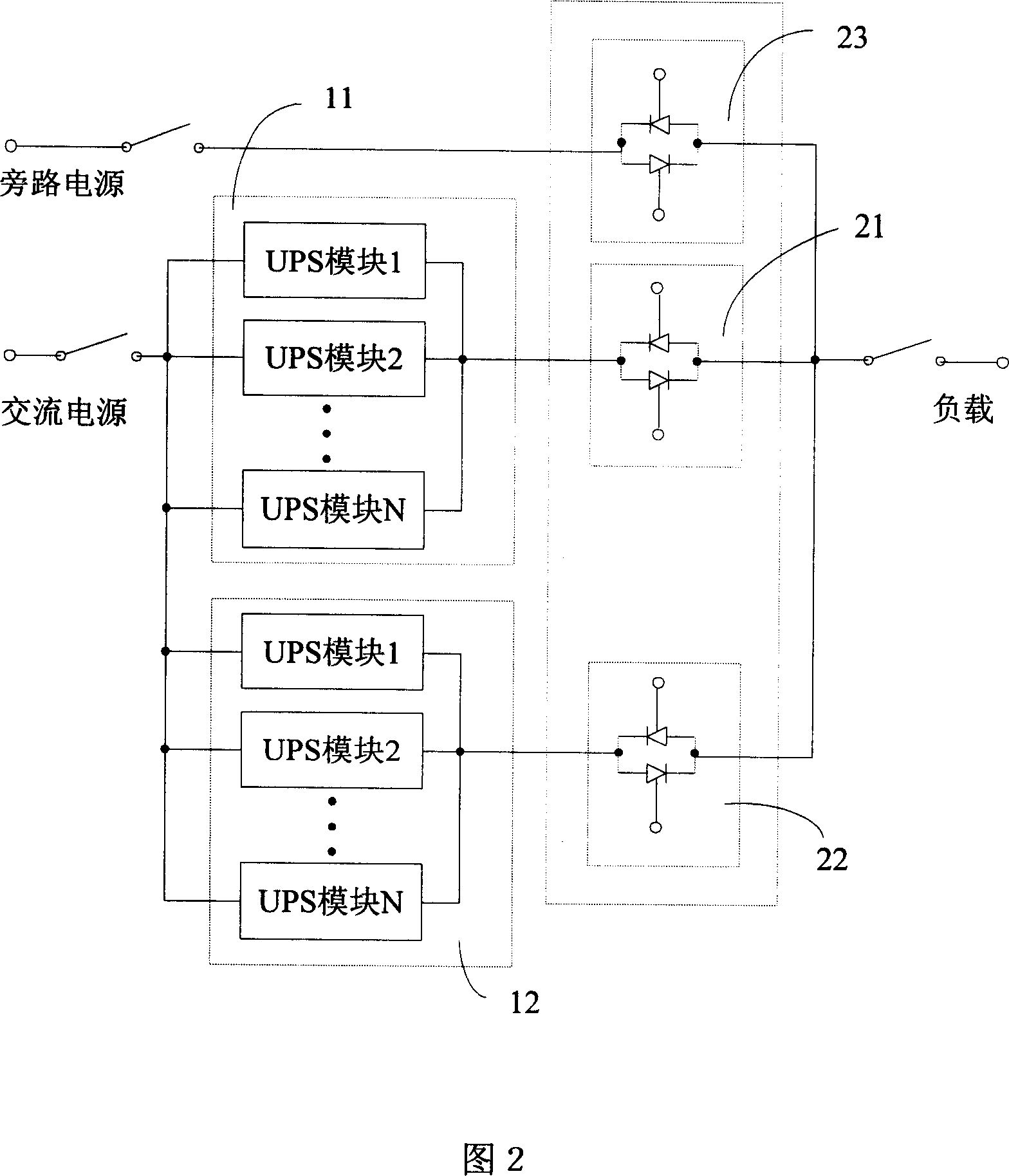
[0015] As shown in Figure 2, in a preferred embodiment of the present invention, an uninterruptible power supply system includes a first UPS (uninterruptible power supply) parallel module 11, a second UPS parallel module 12, a first STS (static transfer switch) switch 21. The second STS switch 22 and the third STS switch 23.

[0016] Wherein, both the first and the second UPS parallel modules include at least two parallel connected UPS modules. Of course, only one UPS module can also be included. The STS switch can be an electronic static transfer switch, a mechanical static transfer switch, or a combination of electronic and mechanical static transfer switches. Three STS switches can be assembled in one module to form an STS module. The above-mentioned STS module can be made into the shape of a drawer, and pins are arranged at the back. When it is needed to u...


PUM


Abstract

This invention discloses an USP system including at least two sets of UPS parallel modules, each of which includes one or at least two parallel UPS modules and static transfer switches in the same number with the UPS parallel module sets, and the inputs of which are coupled with the output ends of the UPS parallel modules. This invention also discloses a configuration method for two kinds of UPS, which sets a supply system a dual-bus mode or a redundant parallel mode, besides, each UPS parallel module and the STS can be set in a supply cabin, so synchronous signals among parallel modules are transmitted easily and the control of the STS module can be integrated into the UPS parallel module.

Description

technical field [0001] The invention relates to a UPS uninterruptible power supply system and a configuration method thereof. Background technique [0002] An existing UPS (Uninterruptable Power Supply, uninterruptible power supply) power supply system usually adopts parallel technology to improve reliability. At present, most commonly used UPS power supply systems use LBS (Load Bus Synchronizer, load synchronization controller) and STS (Static Transfer Switch, static transfer switch) to form a dual-bus power supply structure, as shown in Figure 1. Among them, the LBS detects the output voltage phase of the two UPS systems in real time, and sends a coordination signal to the two UPS power systems, so as to ensure that the power output from the two UPS power systems is always in the "locked state" of mutual synchronous tracking ; The STS switch is used to realize the function of choosing one of the two. When any UPS power supply system fails, the load (LOAD) will be automati...

Claims


Application Information

Patent Timeline
Patent Type & Authority Applications(China)
IPC IPC(8): H02J9/00H02J7/00
Inventor 肖学礼
Owner LIEBERT
Why Eureka
Try Eureka