Non-contact type electrical apparatus line fault testing device

A detection device, non-contact technology, applied in the direction of fault location, line transmission monitoring/testing, line transmission parts, etc., can solve the problems of line fault disassembly, maintenance difficulties, damaged wires, and a lot of time, and achieve fast detection Convenient, small size, easy to carry effect

Inactive Publication Date: 2008-03-05
ZHONGTONG BUS HLDG
View PDF0 Cites 22 Cited by
  • Summary
  • Abstract
  • Description
  • Claims
  • Application Information

AI Technical Summary

Problems solved by technology

[0003] The traditional maintenance method is usually to turn over the drawing, check the technical information, disassemble the circuit and parts, open the outer sheath of the wiring harness, and use the electrician multimeter to measure and search repeatedly in sections. Once the vehicle electrical circuit fails, use the existing traditional In the maintenance method, it takes a lot of time and effort to find the location of the fault by light detection, which is time-consuming and laborious. In addition, the original wire is likely to be damaged due to the misoperation of the maintenance personnel during the inspection of the line section, and a new fault will be formed. Hidden dangers, in the case of increasingly complex existing electrical circuits, traditional maintenance methods are more difficult to disassemble and repair circuit faults

Method used


Image

  • Non-contact type electrical apparatus line fault testing device
  • Non-contact type electrical apparatus line fault testing device
  • Non-contact type electrical apparatus line fault testing device

Examples


Embodiment Construction

[0020] Below in conjunction with accompanying drawing, the present invention is described in further detail:

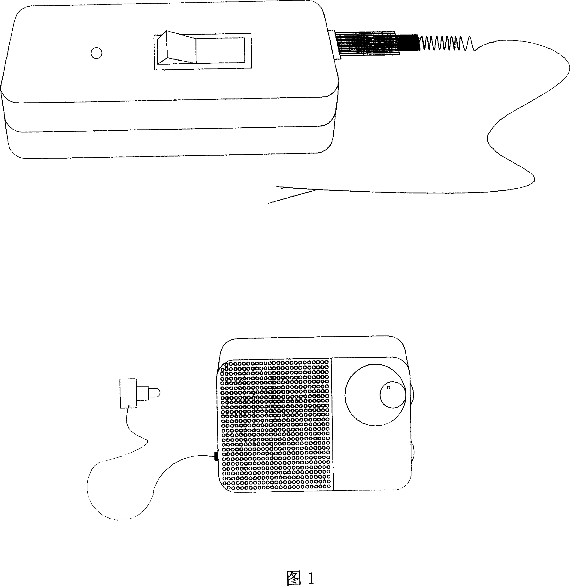
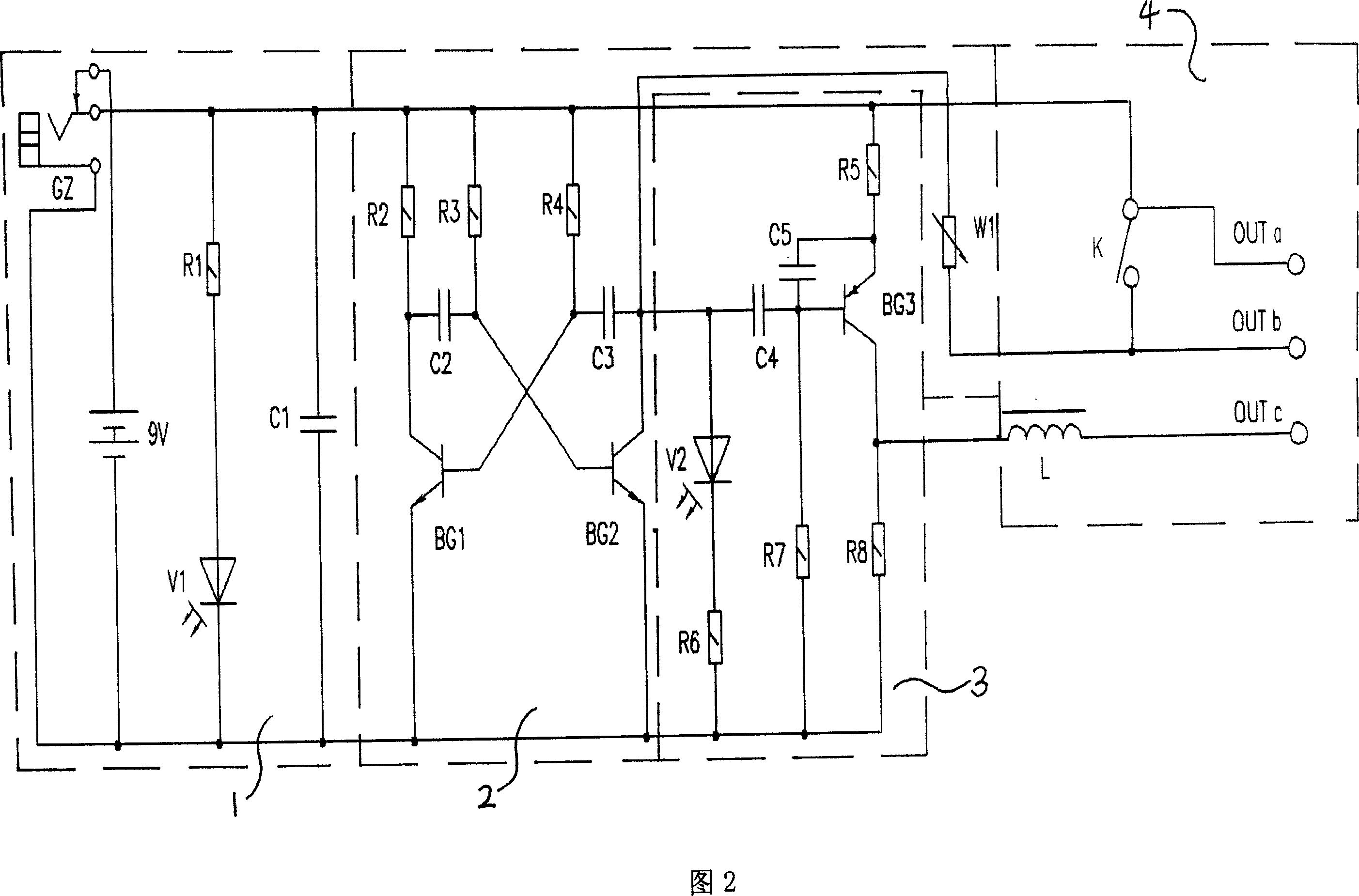
[0021] As shown in Figure 1, Figure 2, and Figure 3,

[0022] Component numbers and names in Figure 2: first resistor R1, 5K; second resistor R2, 5K; third resistor R3, 20K; fourth resistor R4, 20K; fifth resistor R5, 100K; sixth R6, 2K; The seventh resistor R7, 5K; the eighth resistor R8, 2K; the variable potentiometer W1, 10K; the first light-emitting diode V1, the second light-emitting diode V2; the first filter capacitor C1, 0.01uf; the second capacitor C2, 10n ; The third capacitor C3, 10n; the fourth capacitor C4, 15p; the fifth capacitor C5, 10uf; the inductance L; the switch K; the first triode BG1, 9014; Tube BG3, A733; GZ, Φ3.5mm external power socket;

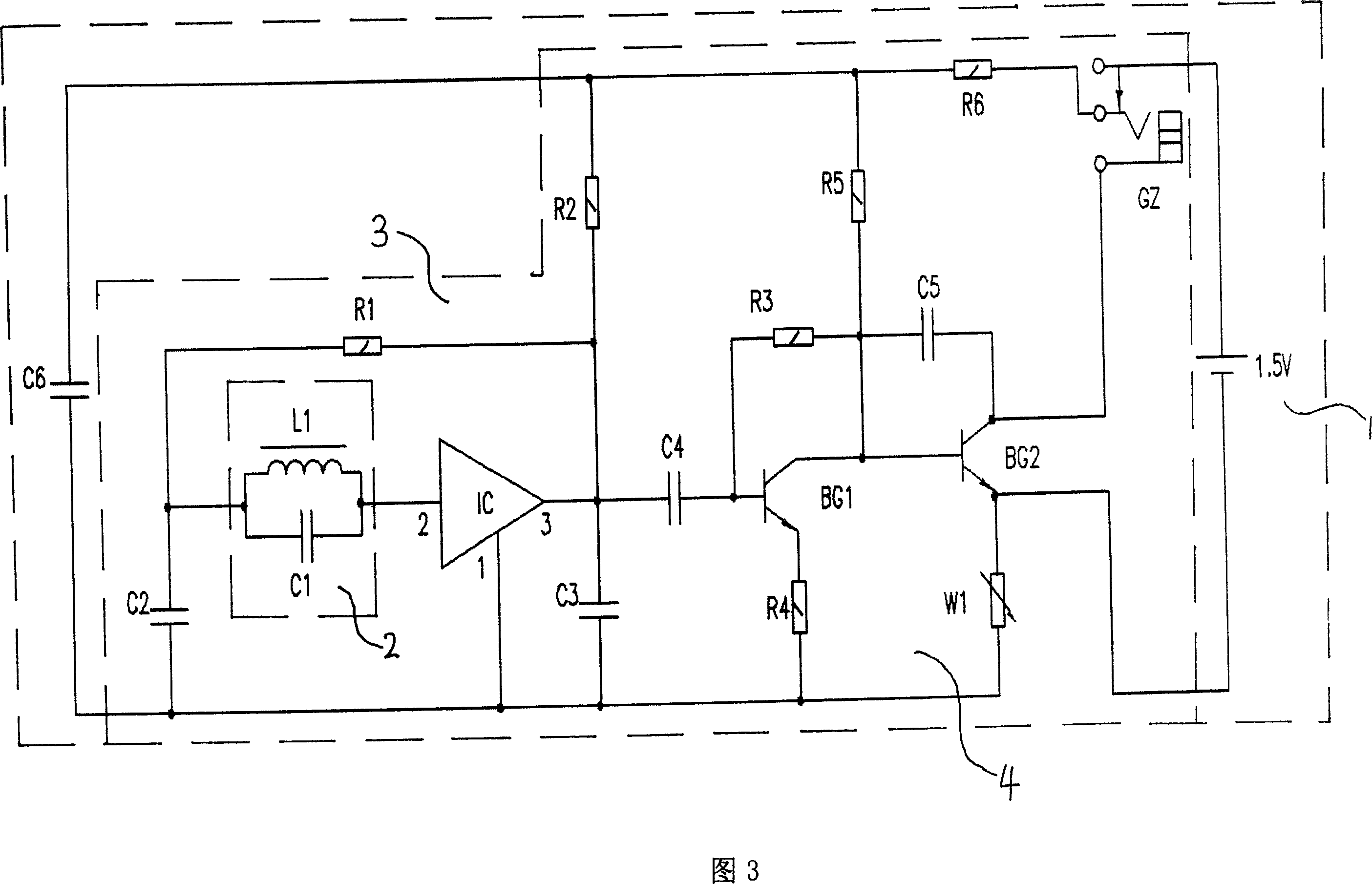
[0023]Component numbers and names in Figure 3: first resistor R1, 100K; second resistor R2, 1.5K; third resistor R3, 27K; fourth R4, 100; fifth resistor R5, 1.5K; adjustable potentiometer W1 , 270; the fi...


PUM


Abstract

This invention relates to a circuit fault test device for non-contacted appliances including a signal generator and a receiver, in which, the signal generation current in the generator generates AC test signals to be transmitted to a being tested circuit by a signal output circuit, and the signal receiver picks up the electromagnetic filed signals around the being tested circuit and varies along the AC test circuit, which monitors and outputs the signals in the mode of changing sound intensity to test if a circuit is normal, which is capable of checking out fault positions without opening ripple tubes or even taking down internal decorations and tracking tend of a wire beam to some hidden circuits in the internal decorations.

Description

technical field [0001] The invention relates to a detection device, in particular to a non-contact electric circuit fault detection device. Background technique [0002] At present, with the improvement and increase of various performances and functions of vehicles such as speed, safety, comfort, and appearance, the number and length of wiring harnesses gradually increase. The technical requirements for the inspection and maintenance of electrical circuits on existing vehicles are higher and more professional, and become a highly professional technical work. [0003] The traditional maintenance method is usually to turn over the drawing, check the technical information, disassemble the circuit and parts, open the outer sheath of the wiring harness, and use the electrician multimeter to measure and search repeatedly in sections. Once the vehicle electrical circuit fails, use the existing traditional In the maintenance method, it takes a lot of time and effort to find the loc...

Claims


Application Information

Patent Timeline
Patent Type & Authority Applications(China)
IPC IPC(8): H04B3/46G01R31/08H04B3/493
Inventor 胡景涵王力刁国栋
Owner ZHONGTONG BUS HLDG
Why Eureka
Try Eureka