Dust control system

A technology for controlling systems and dust, applied in the direction of vacuum cleaners, applications, cleaning machinery, etc., can solve problems such as not being completely effective

Inactive Publication Date: 2008-03-05
TENNANT COMPANY
View PDF0 Cites 26 Cited by
  • Summary
  • Abstract
  • Description
  • Claims
  • Application Information

AI Technical Summary

Problems solved by technology

[0013] Dust exiting the hopper is unavoidable, to help prevent dust from exiting the hopper some form of filter is usually fitted to the air holes, however, usually the dust will be finer than the filter, so this method is not perfectly valid

Method used


Image

  • Dust control system
  • Dust control system
  • Dust control system

Examples


Embodiment Construction

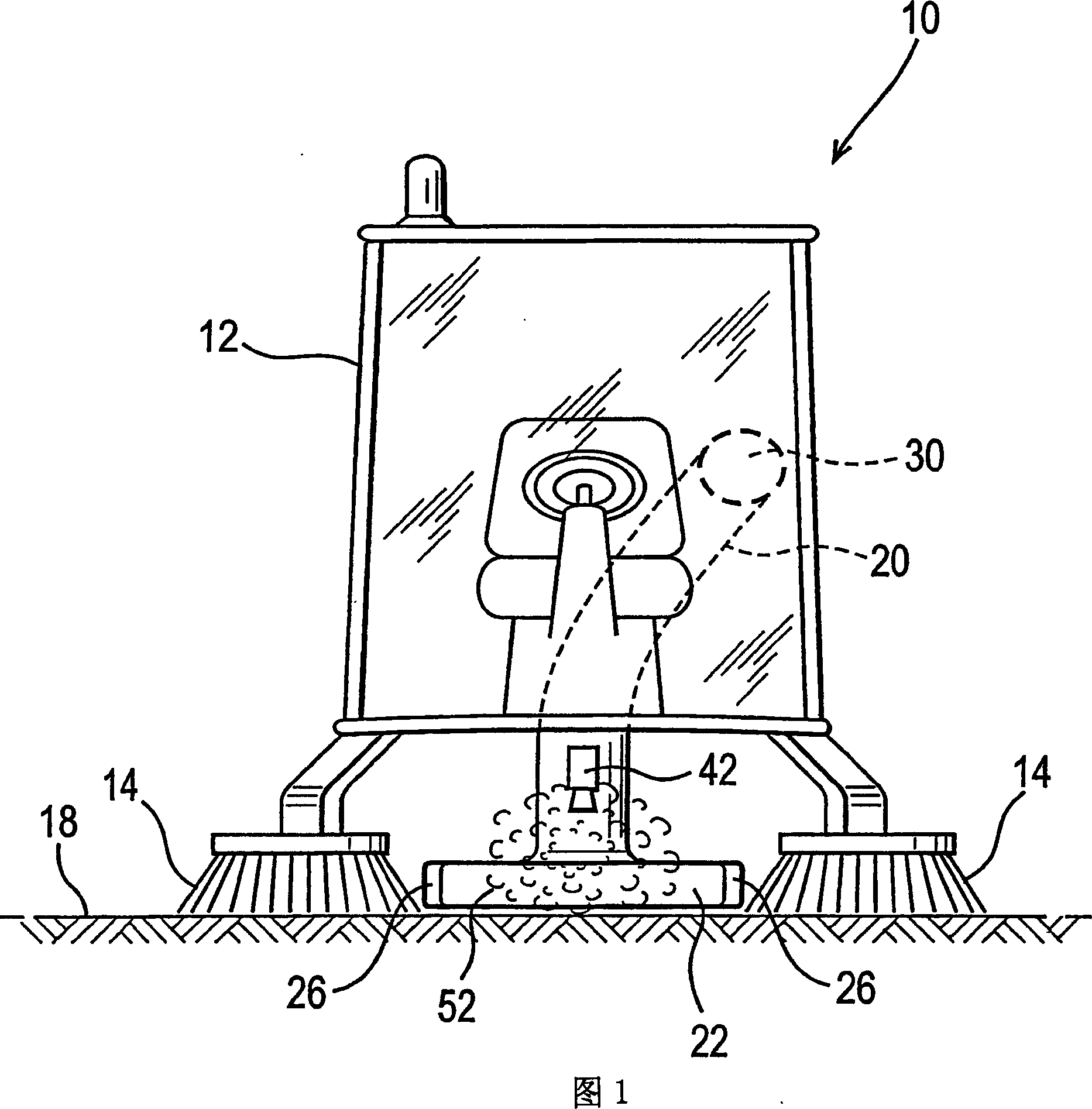
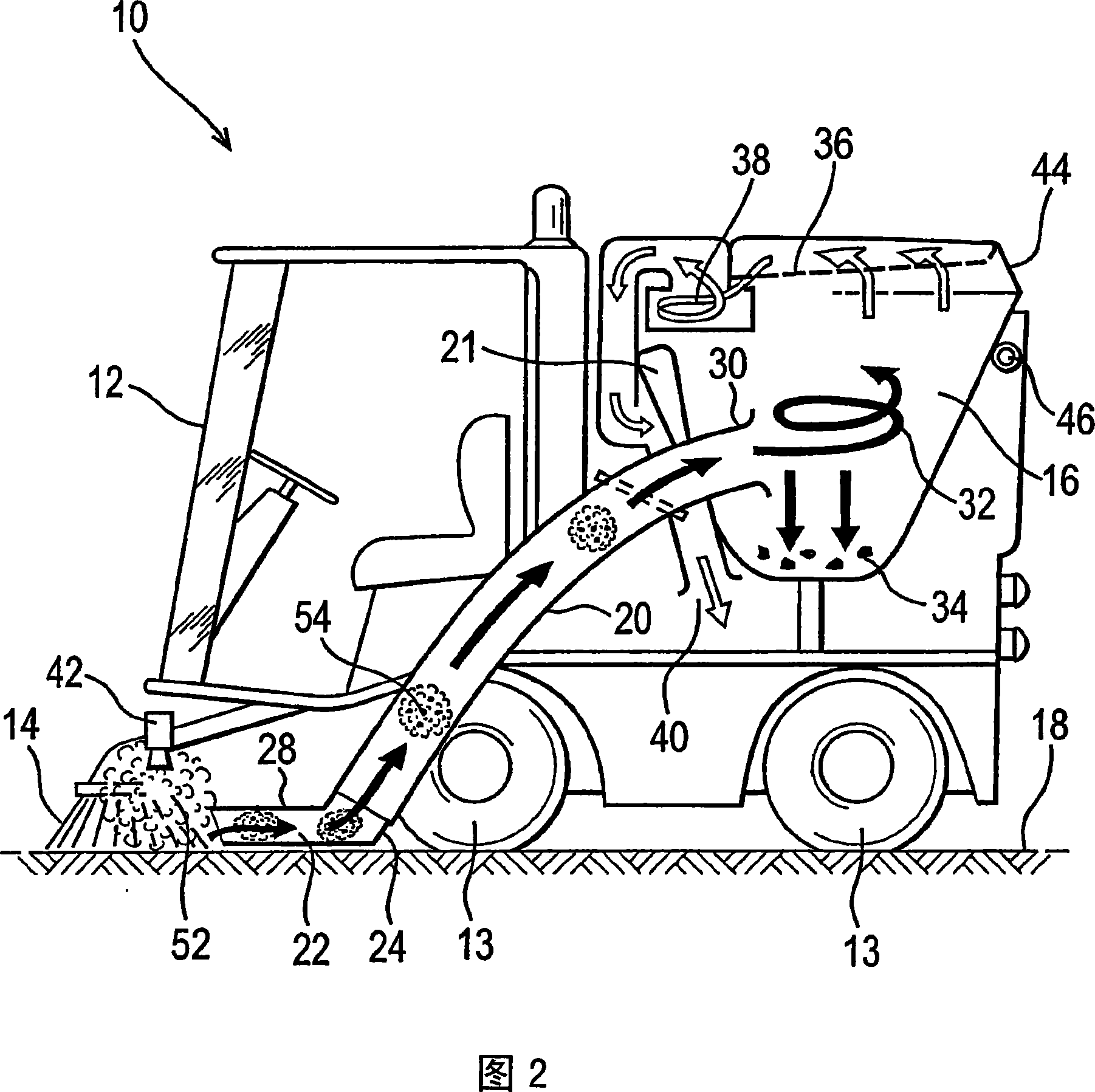
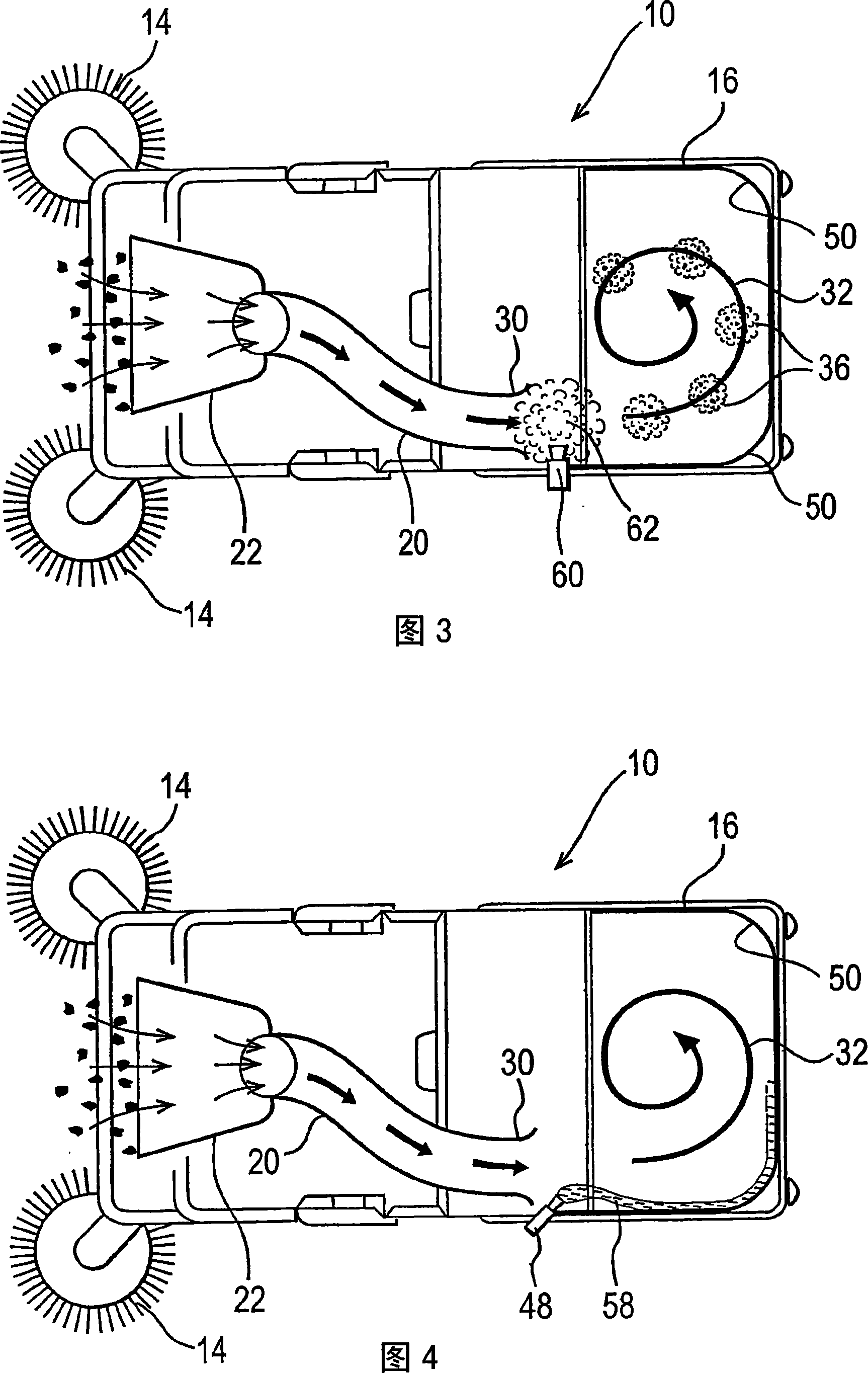
[0070] The present invention provides a road cleaning machine or road sweeping machine (10) fitted with a dust control system using water atomizers (42, 60). Atomizers (42, 60) are fine units for generating water droplets of similar size to dust and enter the dust handling system of the road sweeping machine by entraining the atomized water, e.g. from a brush (14) through a straw (20) Into the hopper (16), dust control is established.

[0071] The illustrated road sweeping machine (10) includes a cab (12), four wheels (13) - two shown, two counter-rotating brushes (14), a bucket (16) (see Figures 2 and 3) ) and a straw (20). The cab (12) is located in front of the machine (10). To sweep dirt off the ground (18), two counter-rotating brushes (14) are located under the cab (12) and slightly forward. The bucket (16) is used to collect dirt and debris off the ground (18). The suction pipe (20) is driven by the blower (21) (see Fig. 2) for sucking up the dirt from the floor (18...


PUM


Abstract

A road cleaning or sweeping machine (10) fitted with a dust control system using a water atomiser (42, 60). The atomiser (42, 60) creates water particles of a similar size to dust, and by entraining atomised water through the road sweeping machine's dust handling systems, i.e. from the brushes (14), through a suction pipe (20) and into a hopper (16), dust control is established. A method of improving dust separation in a hopper (16) of a road sweeping machine (10) using a water atomiser to reduce dust or a spray to wet the walls of the hopper (16).

Description

technical field [0001] The present invention relates to a dust control system, especially a road cleaning machine equipped with a dust control system, or a road sweeping machine. The terms "road cleaning" and "road sweeping" are widely used for the cleaning and sweeping of pedestrian areas (pedestrian precincts), sidewalks, parking lots and other areas. Background technique [0002] A road cleaning machine is a machine that lifts dust off the ground and into a hopper. A road sweeping machine is a road cleaning machine designed to sweep dust from the road, usually towards or into the bucket. In many road sweeping machines, a suction tube (or hose) is provided for sucking in the dirt on the floor being swept, the suction tube has a ground following suction nozzle and the suction tube acts as a conduit to keep those The inhaled dust enters the hopper through the suction tube. However, road cleaning machines only include a straw and bucket, not a sweeping device. [0003] Bu...

Claims


Application Information

Patent Timeline
Patent Type & Authority Applications(China)
IPC IPC(8): E01H1/08A47L11/24A47L9/16A47L11/40
CPCA47L11/4088E01H1/0827A47L11/4013A47L11/24A47L9/1608E01H1/08
Inventor 艾伦·布赖森·利雅查彼德·亚历山大·克拉伦斯·蒙诺克
Owner TENNANT COMPANY
Why Eureka
Try Eureka