Microsystem with electromagnetic control

A microsystem and magnetic technology, applied in the field of microsystems, can solve problems such as reducing the electrical performance of microactuators

Inactive Publication Date: 2010-12-15
SCHNEIDER ELECTRIC IND SAS
View PDF6 Cites 0 Cited by
  • Summary
  • Abstract
  • Description
  • Claims
  • Application Information

AI Technical Summary

Problems solved by technology

The consequence of this heat generation is to degrade the electrical performance of microactuators used as switches, contactors or relays

Method used


Image

  • Microsystem with electromagnetic control
  • Microsystem with electromagnetic control
  • Microsystem with electromagnetic control

Examples


Embodiment Construction

[0034] The present invention will refer to Figure 1-7 Be explained.

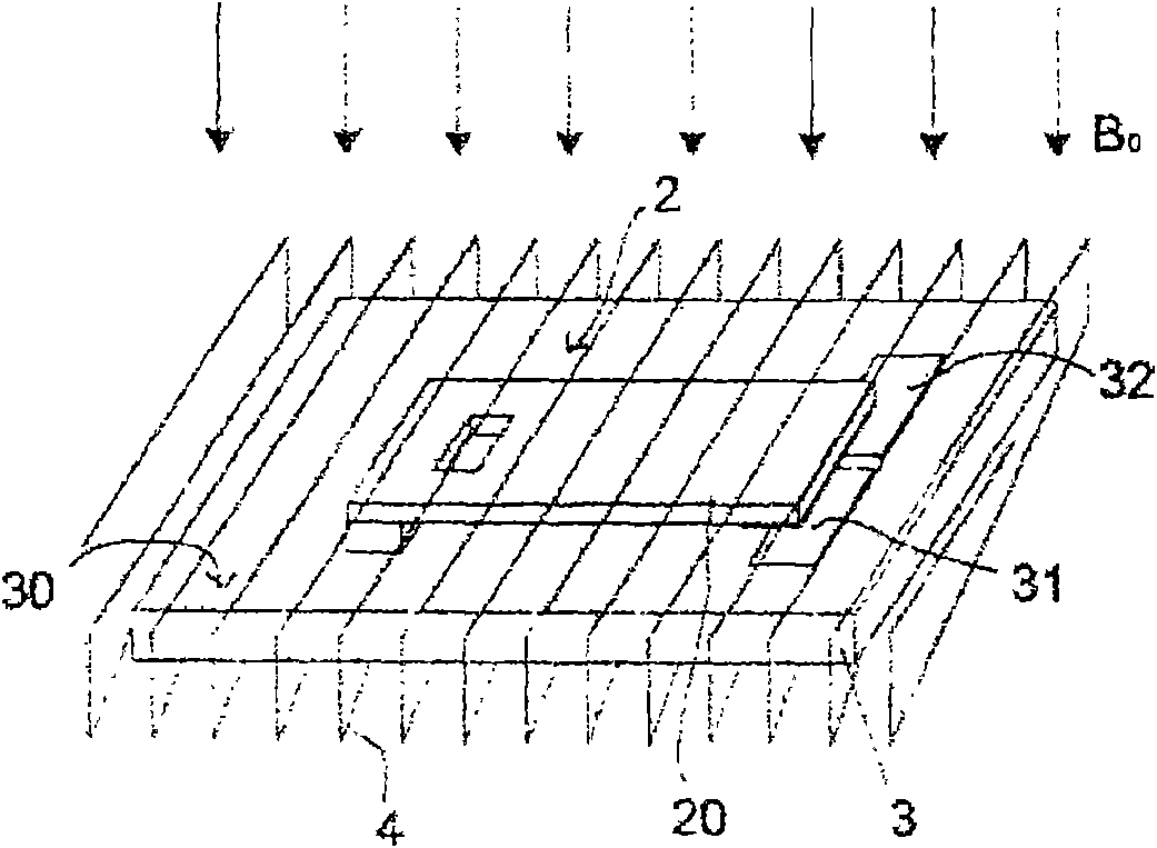
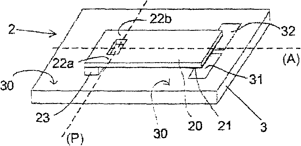
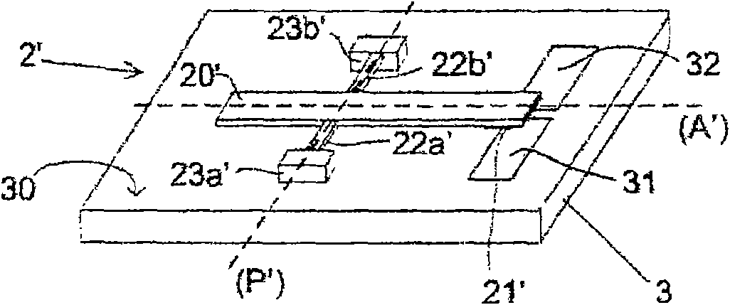
[0035] As described in the prior art above, the microsystem according to the invention uses magnetic microactuators 2, 2' to control the opening or closing of circuits.

[0036] refer to Figure 2A and 2B , the microsystem includes microactuators 2, 2' supported by a substrate 3. The substrate 3 is manufactured, for example, from a material such as glass, plastic or a good thermal conductor based on silicon or ceramics for applying electricity. The substrate 3 has a planar surface 30 on which the microactuators 2, 2' are fixed. As is known (cf. patent application US 2002 / 0140533), the substrate 3 carries eg at least two electrodes 31, 32 for electrical connection to close the electrical circuit ( Figure 2A and 2B ). To achieve this, the magnetic microactuator 2, 2' carries at least one movable contact 21, 21' capable of electrically connecting the two electrodes when the microactuator 2, 2' is activ...


PUM


Abstract

The invention relates to a microsystem, comprising a magnetic microactuator (2, 2''), with a mobile element supported by a substrate (3) and controlled by magnetic effect between a first position and a second position for switching at least one electric circuit, whereby a permanent magnet or a solenoid subjects the mobile element to a first uniform magnetic field (B0) to hold the same in the first position, an energising coil (4, 6), external to the substrate (3), said energising coil (4, 6), on energising the above, submits the mobile element to a second magnetic field (BSi) to move the mobile element from the first position to the second position, the energising coil being of the solenoid type and surrounding the substrate supporting the mobile element.

Description

technical field [0001] The invention relates to a microsystem comprising at least one magnetic microactuator actuated by means of an external excitation coil. Such microsystems can be used as electrical interrupters, especially of the switch, contactor or relay type. Microsystems of this type are particularly suitable for production in MEMs technology. Background technique [0002] Document US 6320145 describes an electrostatic relay. The relay is operated by means of a magnetizable and monostable lever. Under the action of a magnetic field, the rod bends, tending to align in the direction of the magnetic field and close the electrical circuit. Since the rod is made of elastic material, the rod returns to its original position only mechanically when there is no magnetic field / rod interaction. The restoring force on the rod returning it to the original position is therefore of purely mechanical origin and is produced only by the nature of the material used to manufacture ...

Claims


Application Information

Patent Timeline
Patent Type & Authority Patents(China)
IPC IPC(8): H01H50/00
CPCH01H2050/007H01H50/005H01H1/0036H01H2036/0093
Inventor 西尔万·佩纽卡罗琳·库蒂尔阿玛莉亚·加尼尔贝努瓦·格雷普劳伦特·奇西
Owner SCHNEIDER ELECTRIC IND SAS
Why Eureka
Try Eureka