Back light source of planar display heat radiating device

A technology of a flat panel display and a heat dissipation device, which is applied to cooling/heating devices of lighting devices, lighting devices, components of lighting devices, etc., and can solve the problem of low thermal conductivity, reducing the heat dissipation efficiency of the backlight unit 6, and reducing the heat conduction efficiency of the circuit board 7 and other issues, to achieve the effect of prolonging the service life, improving assembly reliability, and improving heat dissipation efficiency

Inactive Publication Date: 2008-03-12
SUNONWEALTH ELECTRIC MACHINE IND
View PDF0 Cites 13 Cited by
  • Summary
  • Abstract
  • Description
  • Claims
  • Application Information

AI Technical Summary

Problems solved by technology

[0005] Generally speaking, the backlight heat dissipation device of the above-mentioned existing flat panel display has the following disadvantages, because the backlight unit 6 does not directly contact the heat dissipation substrate 9 for heat exchange, but indirectly generates heat from the backlight unit 6 through the circuit board 7 The heat energy is conducted to the heat dissipation substrate 9 for heat dissipation, so that the heat dissipation efficiency of the backlight unit 6 is greatly reduced
Furthermore, most of the circuit board 7 is made of a flexible printed circuit board, and its structural material must contain materials with low thermal conductivity (such as: glass fiber, etc.), which will reduce the heat conduction efficiency of the circuit board 7, thereby reducing the backlight. Cooling Efficiency of Unit 6

Method used


Image

  • Back light source of planar display heat radiating device
  • Back light source of planar display heat radiating device
  • Back light source of planar display heat radiating device

Examples


Embodiment Construction

[0022] In order to make the above-mentioned and other purposes, technical features and advantages of the present invention more comprehensible, the preferred embodiments of the present invention are specifically cited below, together with the accompanying drawings, as follows:

[0023] Please refer to Figures 2 and 4, in the first embodiment of the present invention, the backlight cooling device of the flat panel display is preferably combined on the back of a flat panel display (FPD), and the flat panel display a is preferably a liquid crystal display (liquid crystal display, LCD) or plasma display (plasma display panel, PDP), etc., in order to provide light for the backlight and perform heat dissipation at the same time.

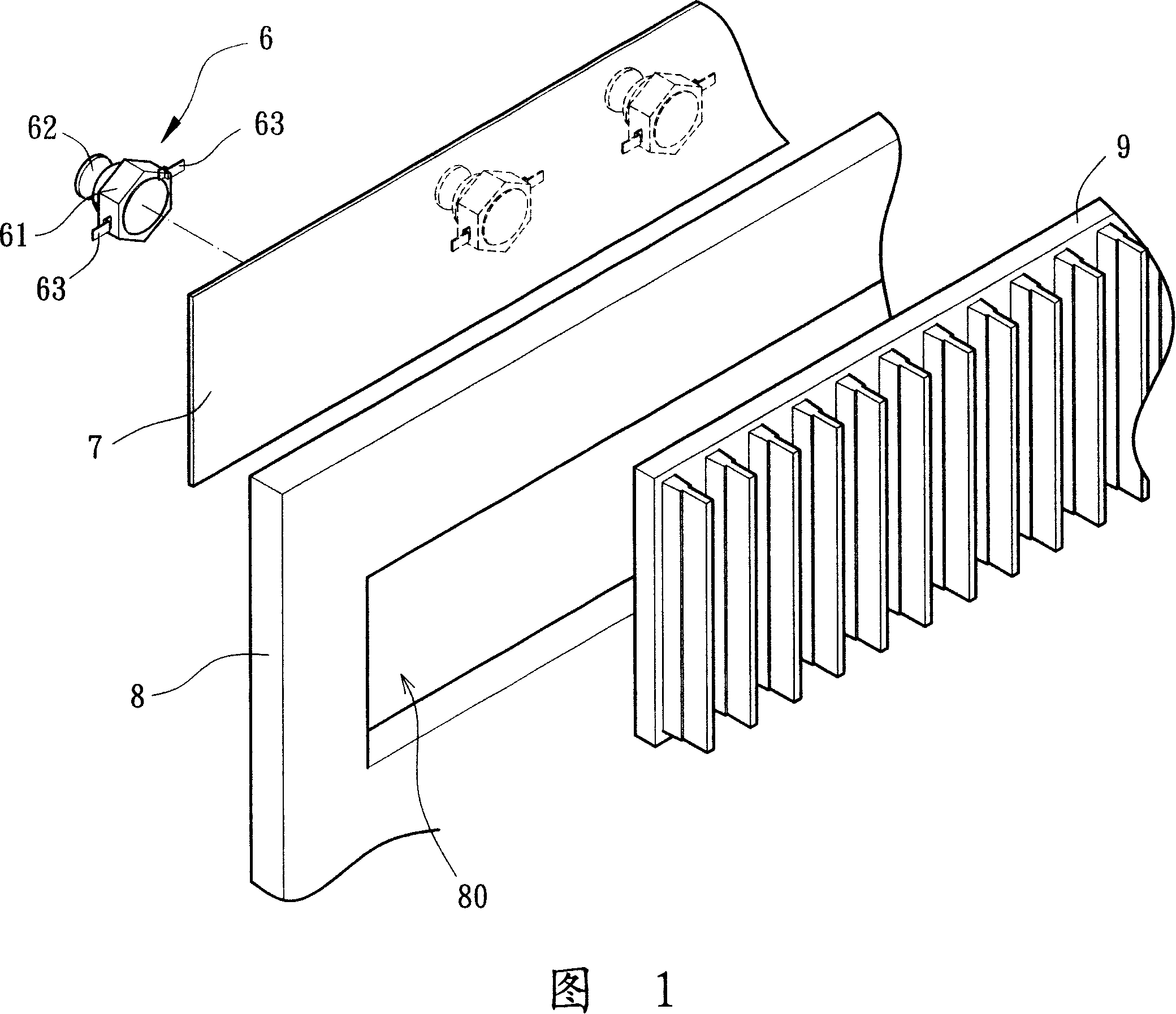
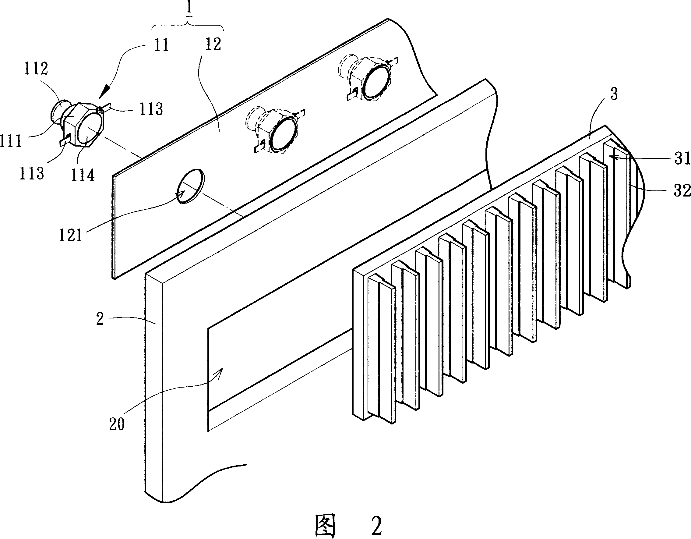
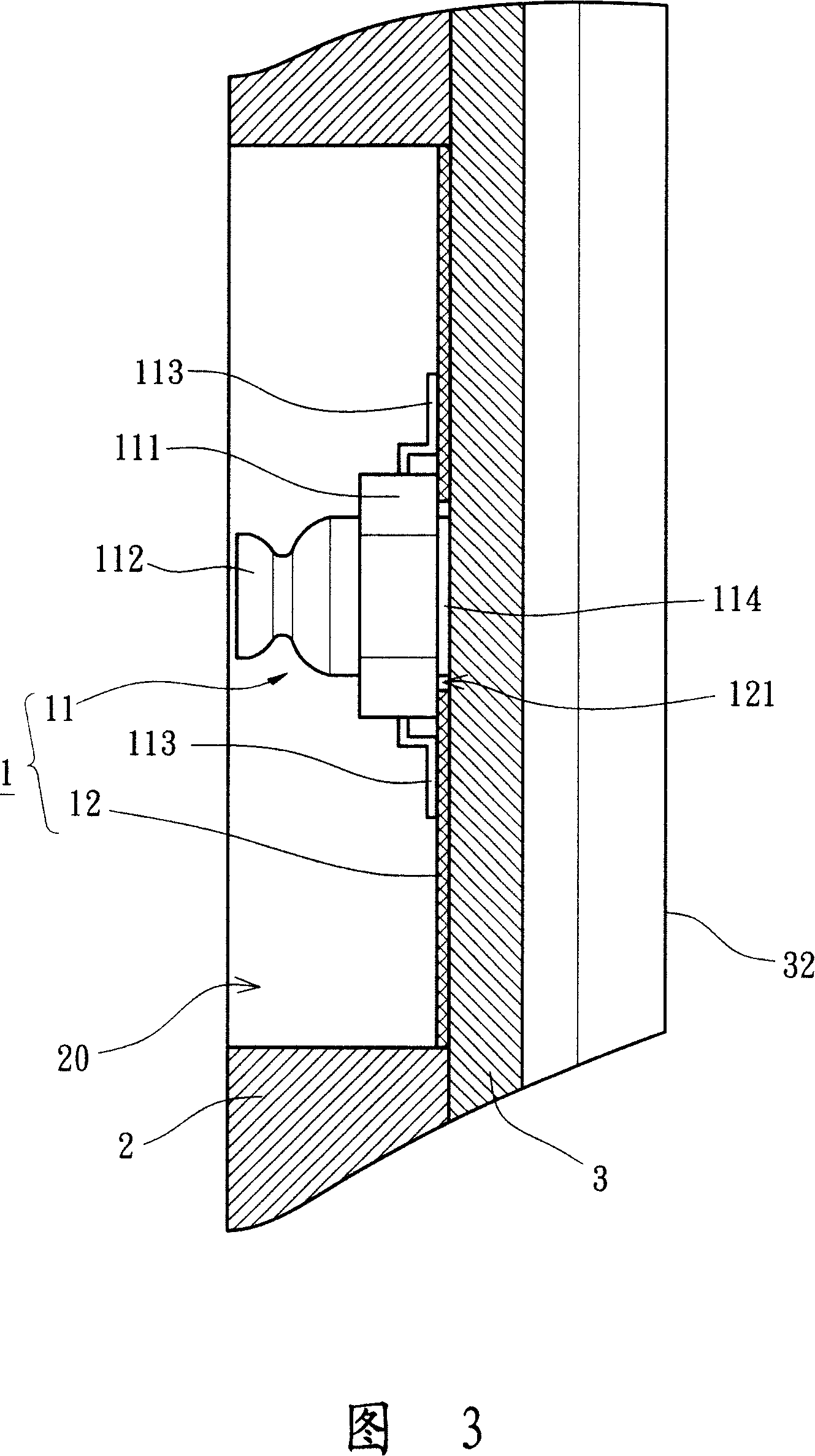
[0024] Please refer to FIGS. 2-3, in the first embodiment of the present invention, the backlight cooling device of the flat panel display includes at least one backlight module 1, a support frame 2 and at least one heat dissipation substrate 3, the backlig...


PUM


Abstract

The invention relates to a back light source radiating device for a flat plane display, which comprises at least a back light unit, a circuit board and a radiating base plate. The back light unit and the circuit board commonly form a back light source module. The back light unit is provided with a luminous element and a heat conducting part, and the heat conducting part is arranged on one end of the luminous element in order to absorb the heat energy produced by the luminous element. The circuit board is arranged on the back of the radiating base plate, and the heat conducting part of the back light unit is directly stuck on the back of the radiating base plate through at least an assembly hole of the circuit board in order that the radiating base plate directly absorbs and dissipates the heat energy produced by the back light source module.

Description

technical field [0001] The invention relates to a backlight heat dissipation device of a flat panel display, in particular to opening at least one assembly hole on a circuit board, and a heat conduction part of at least one backlight unit is directly attached to the back side of a heat dissipation substrate through the assembly hole, so as to achieve A backlight cooling device for a flat panel display with heat dissipation efficiency. Background technique [0002] Please refer to FIG. 1 for a backlight cooling device of a conventional flat panel display, which includes a plurality of backlight units 6 , a circuit board 7 , a supporting frame 8 and a heat dissipation substrate 9 . The backlight unit 6 is disposed on one side of the circuit board 7 and is electrically connected to the circuit board 7 so as to control the backlight unit 6 to provide backlight through the circuit board 7 . The backlight unit 6 has a base 61 , a light emitting element 62 and at least two pole pi...

Claims


Application Information

Patent Timeline
Patent Type & Authority Applications(China)
IPC IPC(8): F21V29/00F21V23/00F21V29/503F21V29/74F21V29/89
Inventor 洪银树刘德真
Owner SUNONWEALTH ELECTRIC MACHINE IND
Why Eureka
Try Eureka