
Remote command line management method of passive optical network terminal

A passive optical network and management method technology, applied in the field of remote command line management interface, can solve the problems of complex implementation and large IP address occupation, and achieve the effects of simple implementation, convenient management and maintenance, and enhanced functions

Inactive Publication Date: 2008-03-12
ZTE CORP
View PDF0 Cites 13 Cited by
  • Summary
  • Abstract
  • Description
  • Claims
  • Application Information

AI Technical Summary

Problems solved by technology

[0008] In view of this, one of the purposes of the present invention is to provide a remote command line management method for passive optical network terminals, which can solve the technical problems of complex implementation and large IP address occupation in existing management methods

Method used


Image

  • Remote command line management method of passive optical network terminal
  • Remote command line management method of passive optical network terminal
  • Remote command line management method of passive optical network terminal

Examples


Embodiment Construction

[0031] Below according to accompanying drawing and embodiment the present invention will be described in further detail:

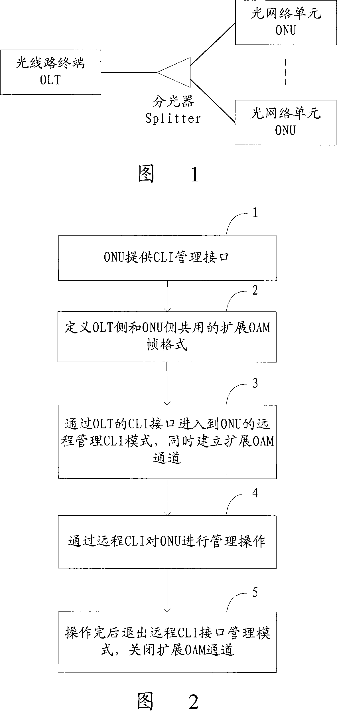
[0032] Fig. 1 has introduced the EPON network topology diagram relevant to the method of the present invention. It can be seen from the figure that an OLT can connect multiple ONUs through an optical splitter. The downlink data transmission method from OLT to ONU is time division multiplexing and physical layer broadcast, that is, each downlink frame will be sent to the PON ports of all ONUs. The uplink data transmission method from the ONU to the OLT is a TDMA (Time Division Multiple Access, Time Division Multiple Access) method.

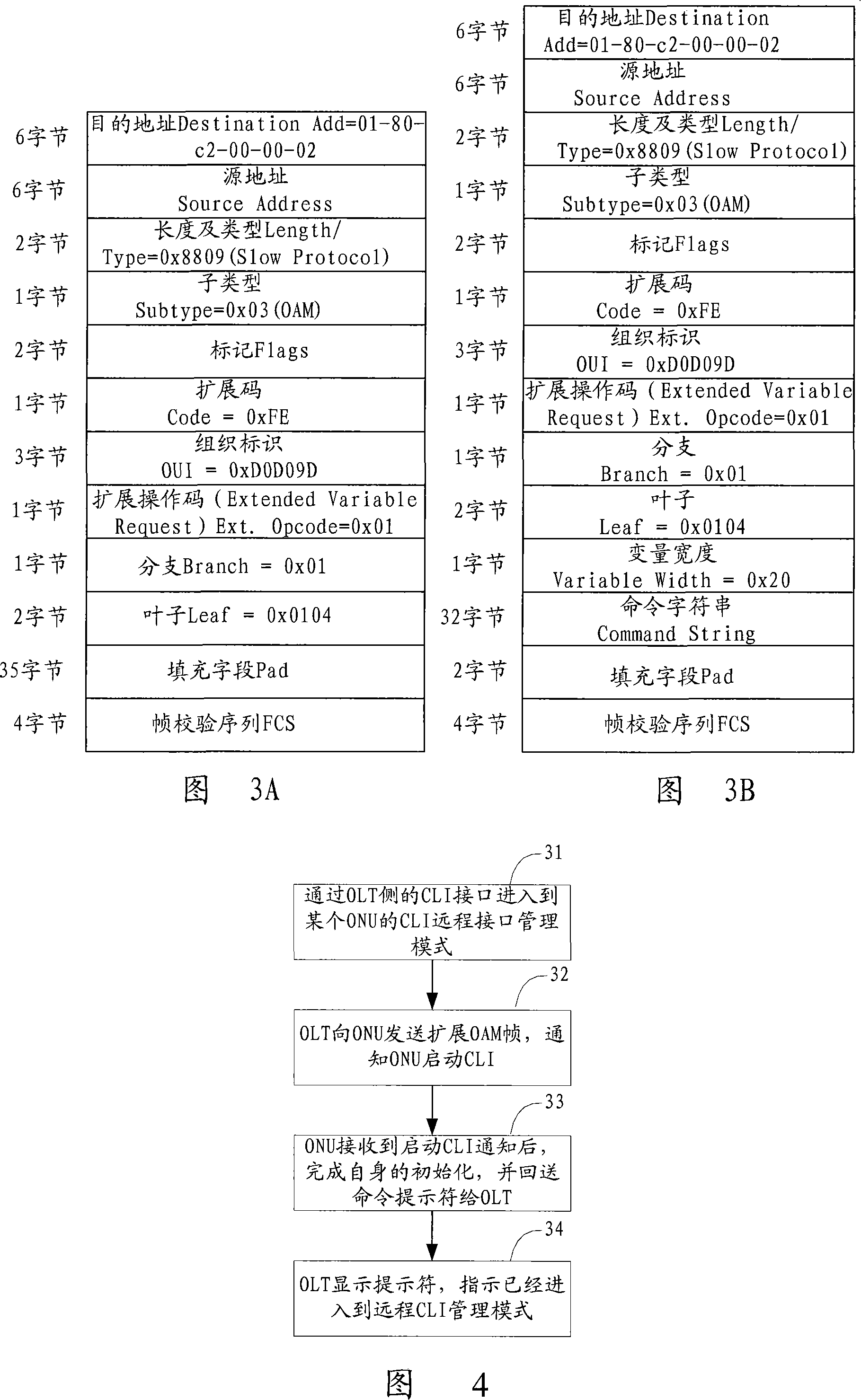
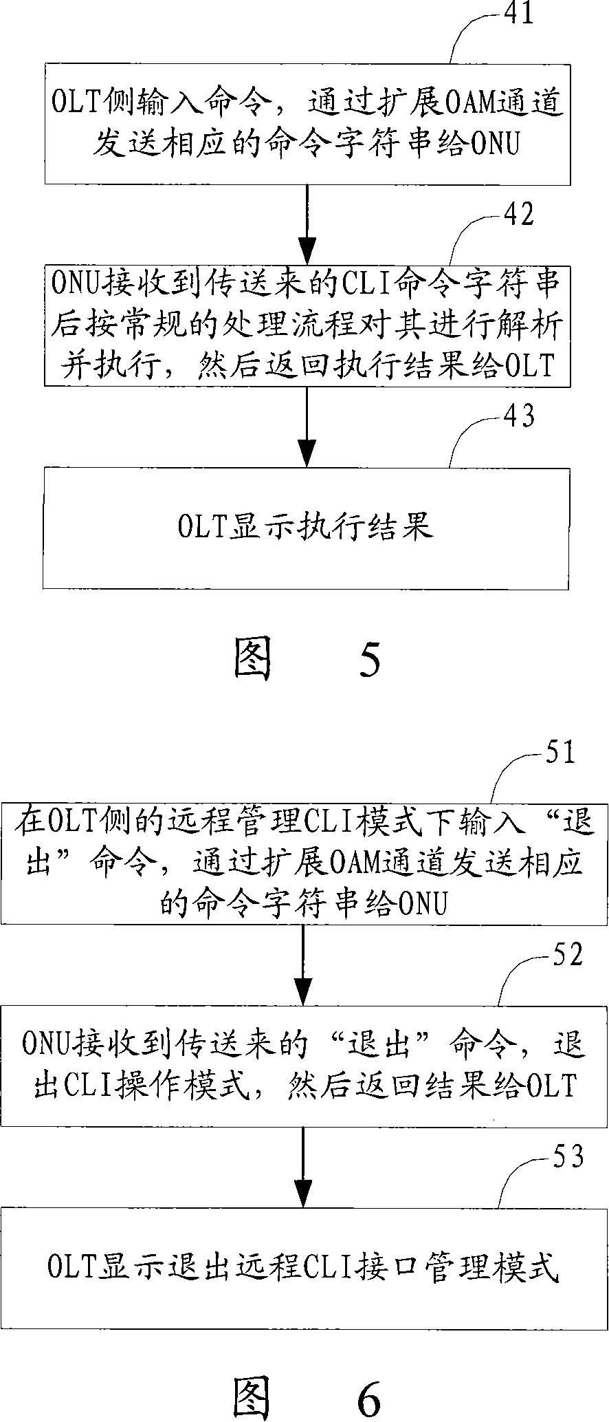
[0033] Fig. 2 is the flow chart of the steps of realizing the method of the present invention, as shown in the figure,

[0034] Step 1. Provide a CLI management interface locally on the ONU.

[0035] The local ONU needs to provide a CLI management interface, and the ONU can be managed through the CLI management interface. Th...


PUM


Abstract

The utility model relates to an Ethernet passive optical network technique, more particularly, a remote command line administration port implementation method used for the Ethernet passive optical network terminal equipment. The utility model solves the complexity and occupation of large volume of IP addresses in the existing management method. The extendable OAM channel is established between OLT and ONU and such channel can be used to conduct the remote command line management. The utility model introduces the straightforward procedures to realize the remote management for ONU, so as to facilitate the management and maintenance of EPON network.

Description

technical field [0001] The present invention relates to a passive optical network (Passive Optical Network, PON) technology, in particular to a method for realizing a remote command line management interface for an Ethernet passive optical network (Ethernet Passive Optical Network, EPON) terminal device. Background technique [0002] Ethernet-based passive optical network technology is a new broadband passive optical network technology based on Ethernet. Its essence is the extension of Ethernet in the field of access network. The central office equipment of EPON, the Optical Line Terminal (OLT), as an access network device, is generally placed in the computer room, while the Optical Network Unit (ONU), as a terminal device, is placed in the A location away from the equipment room, such as the user's home. In view of the long-distance and discrete characteristics of ONU distribution, it is particularly important to carry out unified remote management of ONUs at the central ...

Claims


Application Information

Patent Timeline
Patent Type & Authority Applications(China)
IPC IPC(8): H04L12/24H04L29/06H04L12/28H04B10/00H04Q11/00
Inventor 于金辉唐美玲
Owner ZTE CORP
Learn More