Heat radiating device

A technology of heat sink and heat sink, applied in cooling/ventilation/heating transformation, instrument cooling, instrument and other directions, can solve the problems of low temperature, insufficient heat absorption and heat dissipation of heat sink, insufficient heat dissipation of electronic components, etc. To achieve the effect of improving heat dissipation performance

Inactive Publication Date: 2010-12-29
FU ZHUN PRECISION IND SHENZHEN +1
View PDF3 Cites 0 Cited by
  • Summary
  • Abstract
  • Description
  • Claims
  • Application Information

AI Technical Summary

Problems solved by technology

However, usually only a part of the bottom plate, usually the central part of the bottom plate, is in direct contact with the electronic components and absorbs heat, making the central part of the bottom plate overheated, while other areas on the bottom plate are relatively cold
As a result, the heat sink away from the central area of ​​the bottom plate cannot fully absorb and dissipate heat, and the heat dissipation of electronic components is still not sufficient

Method used


Image

  • Heat radiating device
  • Heat radiating device
  • Heat radiating device

Examples


Embodiment Construction

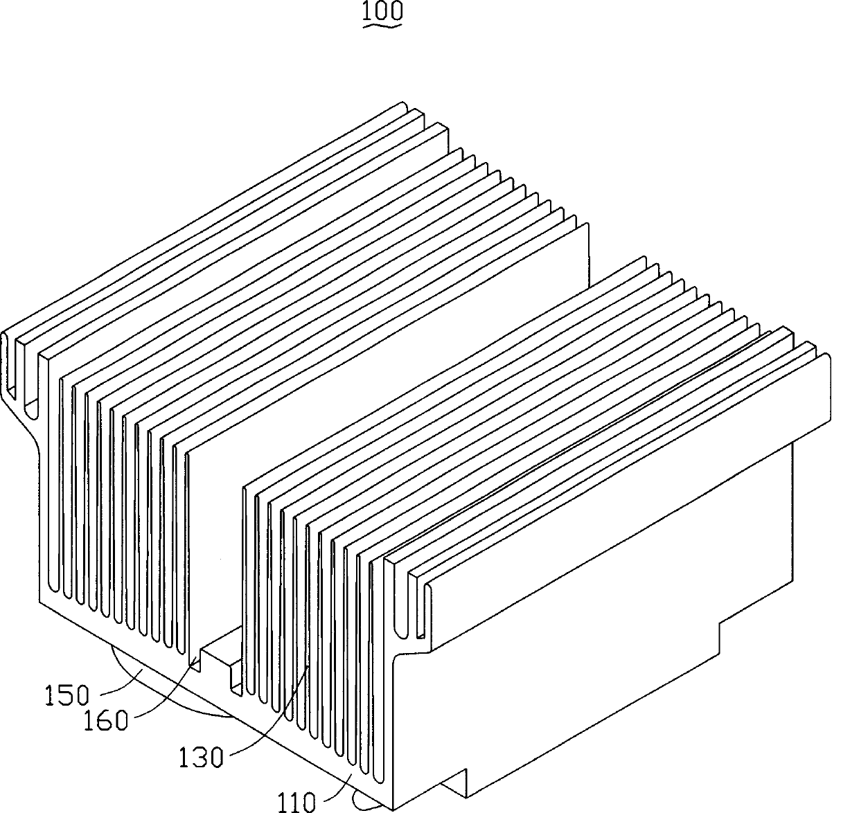
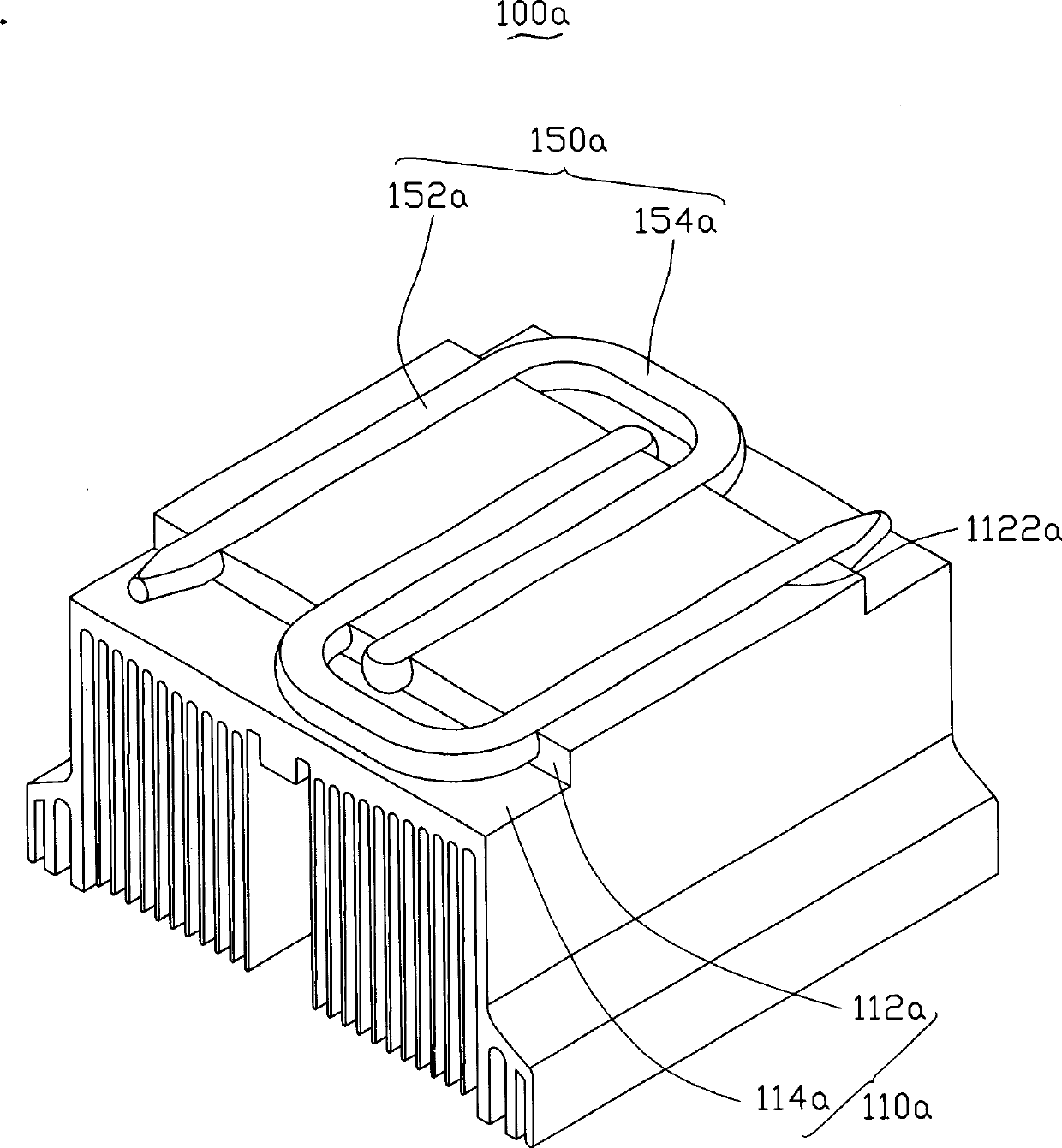
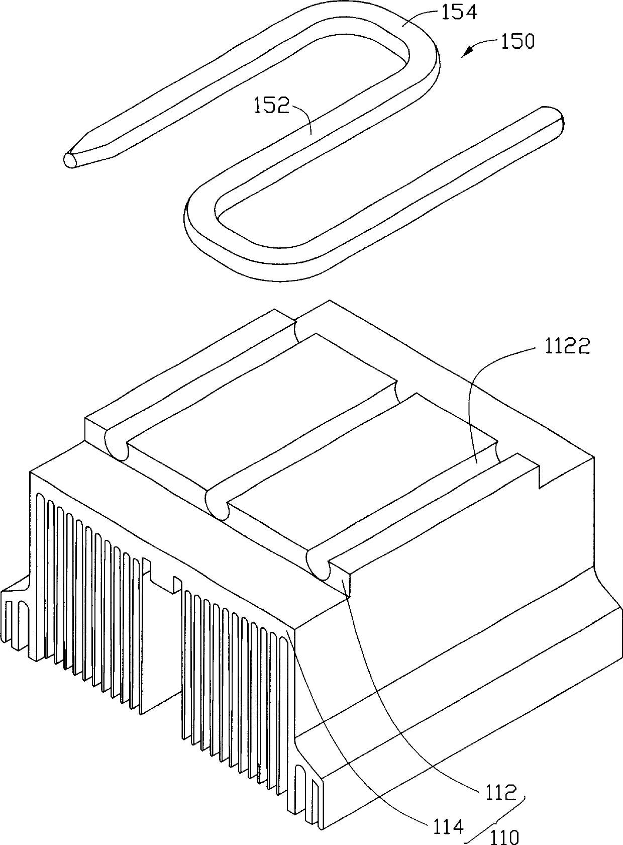
[0012] Figure 1 to Figure 3 Shown is the first embodiment of the heat sink of the present invention. The heat dissipation device 100 includes a base 110, a plurality of heat sinks 130 arranged on the base 110, and an S-shaped heat pipe 150 embedded at the bottom of the base 110.

[0013] The base 110 is made of materials with good thermal conductivity such as aluminum and copper. The base 110 includes two parts, namely a first heat conducting plate 114 and a second heat conducting plate 112 protruding from the middle of the first heat conducting plate 114. The first heat-conducting plate 114 is connected to the heat sink 130, and the bottom surface of the second heat-conducting plate 112 is usually in contact with electronic components such as a central processing unit (not shown) to absorb the heat generated by the electronic components.

[0014] The contours of the first heat conducting plate 114 and the second heat conducting plate 112 are rectangular, and the width of the fi...


PUM


Abstract

The present invention relates to a heat radiating device, which comprises a base seat and a plurality of heat radiating fins arranged on the base seat, the base seat comprises a first heat sink board, the heat radiating fin is arranged on the one side surface of the first heat sink board, Wherein, the base seat also comprises a second heat sink board arranged on the other side surface of the first heat sink board, the width of the second heat sink board is less than the width of the first heat sink board, the heat radiating device also comprises a heat pipe that is inserted on the bottom surface of the second heat sink board and extended out the side direction of the second heat sink board, and extended to the first heat sink board. The heat pipe is inserted on the bottom surface of the second heat sink board in the heat radiating device described in the present invention, the heat pipe not only can be directly touched with an electronic component, the heat quantity generated by the electronic component also can be distributed on the whole base seat uniformly, therefore, compared with the other traditional heat radiating device, the cooling performance of the heat radiating deviceof the present invention is improved greatly.

Description

Technical field [0001] The invention relates to a heat dissipation device, in particular to a heat pipe heat dissipation device for cooling electronic components. Background technique [0002] Electronic components such as the central processing unit generate a lot of heat during operation, which increases the temperature of itself and the system, which in turn leads to a decrease in its operating performance. In order to ensure the normal operation of electronic components, heat dissipation devices are usually installed on the electronic components to dissipate the large amount of heat generated by them. [0003] Traditional heat sinks generally include a bottom plate contacting electronic components and a number of heat sinks arranged on the bottom plate. After the heat generated by the operation of the electronic components is absorbed by the bottom plate, it is lost to the surrounding environment through the heat sink to cool the electronic components. However, there is usual...

Claims


Application Information

Patent Timeline
Patent Type & Authority Patents(China)
IPC IPC(8): H05K7/20G06F1/20G12B15/06H01L23/427
Inventor 赖振田周志勇刘宜三
Owner FU ZHUN PRECISION IND SHENZHEN
Why Eureka
Try Eureka