A cold-shear shearing device and shearing process for finish-rolled rebar

A technology of precision-rolled rebar and shearing device, which is applied in the field of rebar, can solve the problems of easy bending, unsmooth feeding, and long time consumption, and achieve the effects of ensuring feeding, reducing arrangement time, and improving support stability

Active Publication Date: 2022-03-04
JIANGSU BINXIN STEEL GRP
View PDF23 Cites 0 Cited by
  • Summary
  • Abstract
  • Description
  • Claims
  • Application Information

AI Technical Summary

Problems solved by technology

[0003] The existing rebar shearing device mainly has the following technical problems during use: one is that the waste produced in the rebar shearing is directly scattered on the ground of the construction site. It is not easy to clean, and kicking will cause foot injuries; second, the rebar needs to be manually arranged according to the grooves on the fixing device before cutting, so that it can be aligned with the grooves in the fixing device, but manual alignment is time-consuming It is long and inconvenient to use; the third is that the rebar is easy to bend under its own gravity during the feeding process, causing unsmooth feeding

Method used


Image

  • A cold-shear shearing device and shearing process for finish-rolled rebar
  • A cold-shear shearing device and shearing process for finish-rolled rebar
  • A cold-shear shearing device and shearing process for finish-rolled rebar

Examples


Embodiment 1

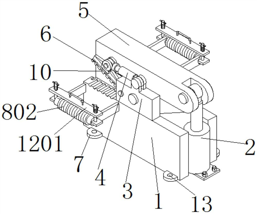
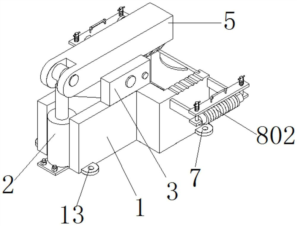
[0042] Embodiment 1 has introduced a kind of finish-rolled rebar cold shear shearing device and shearing process, as Figure 1-3 As shown, it includes a base 1, an electric telescopic rod one 2, a support seat 3, an electric telescopic rod two 4, a shear knife 5 and a fixed arm 6, and the shearing device also includes a fixed foot 7, an auxiliary support assembly 8 and a rebar Storage component 9;

[0043] There is a pair of bases 1, and a support base 3 is fixedly connected to the central position of the upper surface of a pair of bases 1, and the shearing knife 5 is connected to a pair of support bases 3 in rotation, and the support base 3 Rotationally connected to the middle position of the shearing knife 5; one end of the shearing knife 5 is rotationally connected to the top of the electric telescopic rod-2, and the bottom end of the electric telescopic rod-2 is fixedly connected to the ground through a connecting plate and bolts On: the upper surface of the support base ...

Embodiment 2

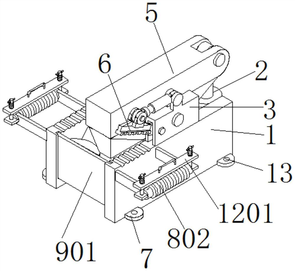
[0054] Embodiment 2 is an improvement on the basis of Embodiment 1, as Figure 7-8 As shown, wherein, a pair of the bases 1 are equipped with a threaded steel storage assembly 9, and the threaded steel storage assembly 9 includes a collection slope 901 and a baffle 902, and the two sides of the collection slope 901 are respectively fixedly connected to On the side of a base 1; a pair of inner sides of the base 1 are provided with a vertical chute 903, and the chute 903 extends vertically downward from the upper surface of the base 1 to the collection swash plate 901. The two sides of the baffle plate 902 are respectively snapped into a chute 903 and the baffle plate 902 can slide freely in the vertical direction along the chute 903; The top surface of the baffle plate 902 is in close contact with;

[0055] In this embodiment, the present invention can collect the cut threaded steel waste by setting the collecting inclined plate and the baffle plate 902. The baffle plate 902 i...

Embodiment 3

[0062] Embodiment 3 is an improvement on the basis of Embodiment 2, as Figure 9-10 As shown, the lower surface of the limiting plate 1201 is fixedly connected with several limiting protruding blocks 17 , and each of the limiting protruding blocks 17 is located directly above a limiting groove 3 16 .

[0063] In this embodiment, the lower surface of the limiting plate 1201 is fixedly connected with a number of limiting protruding blocks 17 and the limiting protruding blocks 17 are in one-to-one correspondence with the limiting groove three 16. The threaded steel is fixed, so that the threaded steel is stably engaged in the third limiting groove 16.

[0064] Embodiment 3 provides a shearing process for finishing-rolled rebar cold shear shearing device shearing finish-rolled rebar, and the shearing process includes the following steps:

[0065] Step 1, conveying the rebar to the auxiliary support roller 802 through the conveyor belt;

[0066] Step 2, the rebars are evenly dist...


PUM


Abstract

The invention provides a cold-shear shearing device and shearing process for fine-rolled threaded steel, which relate to the technical field of threaded steel bars, including a base, an electric telescopic rod one, a support seat, an electric telescopic rod two, shear knives, a fixed arm, and a fixed foot , auxiliary support assembly and rebar storage assembly; the present invention can reduce the arranging time of rebar by offering a limited slot 1 on the base; by being fixedly connected with a lifting rod and a support roller on the outside of the base, it can not only prevent the entering shear The rebar in the cutting area is supported, and it can also support the cut rebar section, so that the rebar is always in a horizontal state during the cutting process, without manual support, ensuring smooth feeding; by setting the limit plate , can prevent the threaded steel from falling off from the support roller, the present invention can collect the cut threaded steel waste by setting the collecting sloping plate and the baffle plate, and the baffle plate and the base are connected by sliding to facilitate the disassembly of the baffle plate.

Description

technical field [0001] The invention belongs to the technical field of threaded steel bars, in particular to a cold-shear shearing device and a shearing process for finished-rolled threaded steel bars. Background technique [0002] Rebar, also known as cold-rolled ribbed steel bar, refers to a steel material that forms a two-sided or three-sided crescent on the surface of the steel by a pair of rolls. The hardness of the rebar is high, and the rebar embedded in the concrete material has a great supporting force, so the rebar is widely used in construction. The rebar shearing device can cut the rebar installation target length, or remove the end of the rebar that does not meet the construction requirements. [0003] The existing rebar shearing device mainly has the following technical problems during use: one is that the waste produced in the rebar shearing is directly scattered on the ground of the construction site. It is not easy to clean, and kicking will cause foot inj...

Claims


Application Information

Patent Timeline
Patent Type & Authority Patents(China)
IPC IPC(8): B23D33/02B23D17/00B23D33/00
CPCB23D33/02B23D17/00B23D33/00
Inventor 王晓东张树江刘刚周文君孟宪新
Owner JIANGSU BINXIN STEEL GRP
Why Eureka
Try Eureka