
Novel high temperature fan

A high temperature, fan technology, used in mechanical equipment, machines/engines, liquid fuel engines, etc.

Inactive Publication Date: 2008-03-19
SHANGHAI GENERAL FAN
View PDF0 Cites 8 Cited by
  • Summary
  • Abstract
  • Description
  • Claims
  • Application Information

AI Technical Summary

Problems solved by technology

The existing technology mainly isolates the volute and impeller of the high-temperature fan from the motor and power transmission part with a heat insulation layer, but since the impeller shaft is connected to the power transmission part, its heat transmission can transfer heat to the power transmission part , and due to the action of the impeller, high temperature and high pressure hot air will also enter the power transmission part from the gap of the transmission shaft

Method used


Image

  • Novel high temperature fan

Examples


Embodiment Construction

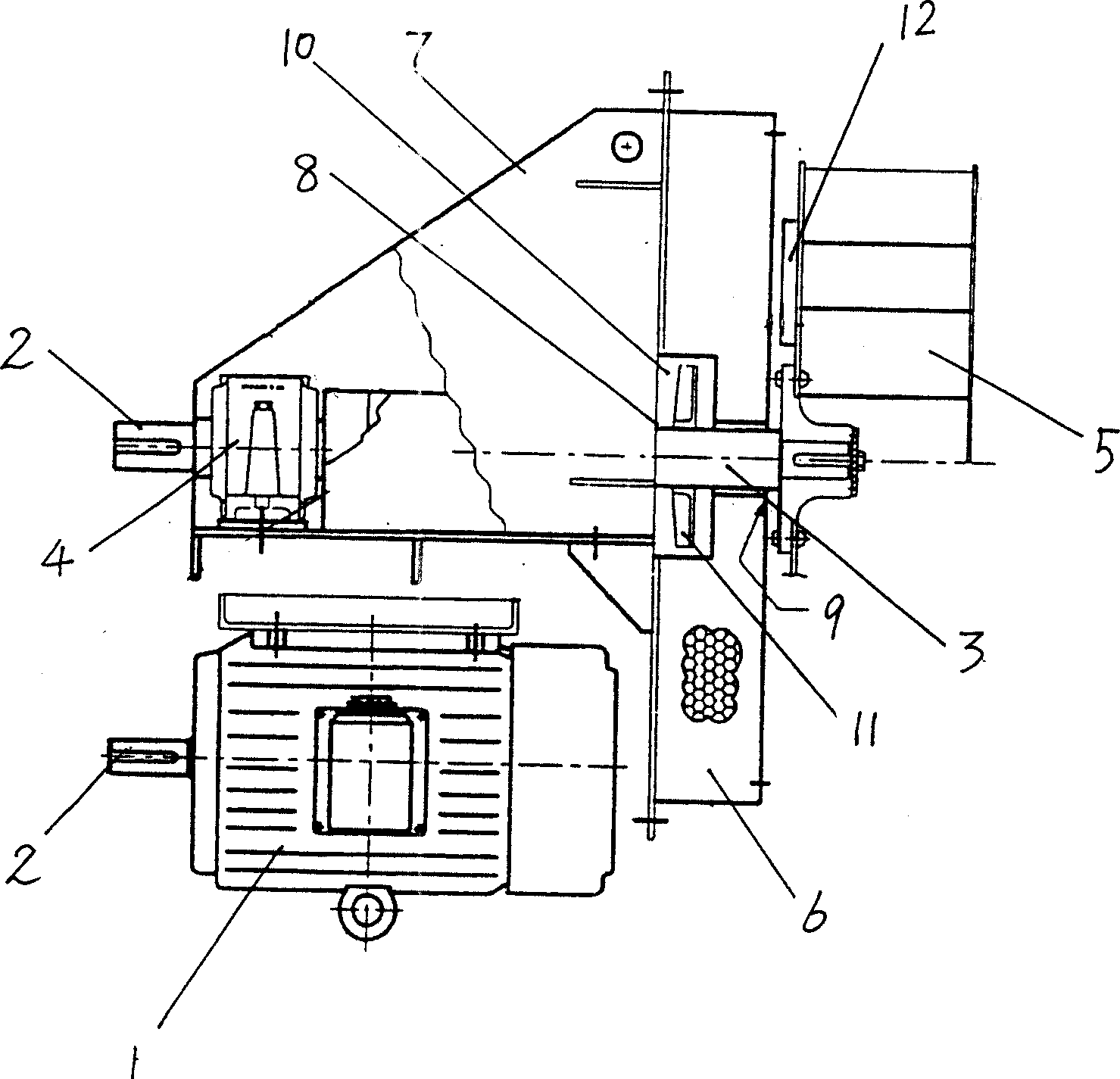
[0006] It includes a motor 1, a belt drive 2, a main shaft 3, a bearing seat 4, an impeller 5, and a heat insulation layer 6. It is characterized in that: the belt drive 2, the main shaft 3, and the bearing seat 4 are located in a frame 7, and the main shaft 3 is guided by the frame 7. The hole 8 extends out to connect the impeller 5, the outer side of the frame 7 is a heat insulation layer 6, and the outer side of the shaft hole 8 of the frame 7 has a sealing ring 9, the sealing ring 9 is tangent to the main shaft 3, and there is an inner sink on the inner side of the heat insulating layer 6 The circular groove 10 has a vane 11 on the main shaft 3, and the vane 11 is located in the sunken circular groove 10, and there are small blades 12 on the impeller 5 facing the heat insulation layer 6 side. The air discharge direction of the vane 11 faces away from the impeller 5 .

[0007] During actual installation, the motor 1 is located on one side of the heat insulation layer 6 and ...


PUM


Abstract

The invention relates to a novel high temperature air blower. The invention comprises a motor, a belt transmission, a main axle, a bearing seat, an impeller, and a heat isolation layer, and the invention is characterized in that the belt transmission and the main axle and the bearing seat are positioned in a frame, the main axle is extended in the frame via the axle hole and connected with the impeller, the heat isolation layer is arranged at the outside of the frame, a sealing ring is arranged at the outer side of the axle hole of the frame, the sealing ring is tangential with the main axle, an inner sunken round groove is arranged at the inner side of the heat isolation layer, a fan blade is arranged on the main axle, the fan blade is positioned in the inner sunken round groove, and a small blade is arranged at the side where the impeller faces the heat isolation layer. The air exhaust direction of the fan blade is back to the impeller. The invention has the advantages that the heat of the high temperature area of the impeller can be isolated, to prevent disadvantageous influence of high temperature to the normal running of the motor and the power transmission part.

Description

technical field [0001] The invention relates to a fan, in particular to a novel high-temperature fan. Background technique [0002] At present, in metallurgy, casting, food processing and other industries in industrial production, high-temperature fans are needed for air supply and exhaust. Because during high-temperature air supply and exhaust, high-temperature gas is easy to be blown by air flow and the connecting part of the fan's own shaft. It is transmitted to the power transmission part, thereby affecting the normal operation of the high-temperature fan. Therefore, how to isolate the heat transfer of the high-temperature fan is the key to ensure the normal operation of the high-temperature fan. The existing technology mainly isolates the volute and impeller of the high-temperature fan from the motor and power transmission part with a heat insulation layer, but since the impeller shaft is connected to the power transmission part, its heat transmission can transfer heat ...

Claims


Application Information

Patent Timeline
IPC IPC(8): F04D29/58F04D25/08
Inventor 金德发周天尧蒋红卫
Owner SHANGHAI GENERAL FAN
Learn More